基于VHDL语言的状态机(FSM)设计
状态机(Finite State Machine,FSM)
状态机的组成:如图所示![[外链图片转存失败,源站可能有防盗链机制,建议将图片保存下来直接上传(img-ur7YnvA2-1589528869675)(G:\研究生\FPGA课程\笔记文档\rec\091852508161862.jpg)]](https://img-blog.csdnimg.cn/20200515154641790.jpg?x-oss-process=image/watermark,type_ZmFuZ3poZW5naGVpdGk,shadow_10,text_aHR0cHM6Ly9ibG9nLmNzZG4ubmV0L3FxXzE3MTE5MjY3,size_16,color_FFFFFF,t_70#pic_center)
状态机的种类:
- Mealy型:当前状态、当前输入相关
- Moore型:仅当前状态相关
- VHDL代码结构:
- 时序逻辑部分:process内部
- 组合逻辑部分: 在使用FSM方式设计VHDL代码时,通常会在结构体的开始部分插入一个用户自定义的枚举数据类型,其中包含所有可能出现的电路状态。
设计风格1
一种结构清晰、易于实现的FSM设计风格:
- FSM中的时序逻辑部分和组合逻辑部分分别独立设计;
- 定义一个枚举数据类型,内部包含所有FSM需要的状态;
FSM中时序逻辑部分的设计特点:
- 确定的输入/输出端口
- 典型的模板可供使用
- 标准的设计
- 寄存器数目少:默认的编码方式下,log2n,N表示状态数,表现为位宽
------------lower section---------------
process (clock, reset)
beginif (reset = '1‘)  thenpr_state <= state0;elsif (clock’event and clock=‘1’)  thenpr_state <= nx_state;end if;
end process;
FSM中组合逻辑部分的设计特点:
- 并发代码、顺序代码皆可;
- 顺序代码方式的设计模板;
- process的敏感信号列表;
- 完整列出IN/OUT组合;
- 无边沿赋值,无寄存器生成;
------------upper section---------------
process (input, pr_state)
begincase pr_state iswhen state0=>        //多个条件转移分支if  (input=...)  thenoutput <= <value>;nx_state<=state1;else  ....;end if;when  state1=>if  (input=...)  thenoutput <= <value>;nx_state<=state2;else  ....;end if;......end case;
end process;
状态机模板
library ieee;
use ieee.std_logic_1164.all;
entity <entity_name> isport (input: in <data_type>;reset, clock: in std_logic;output: out <data_type>);
end <entity_name>;
architecture <arch_name> of <entity_name> istype state is (state0, state1, state2, state3, ...);signal pr_state, nx_state: state;
begin
------------lower section---------------
process (clock, reset)
beginif (reset = '1')  thenpr_state <= state0;elsif (clock'event and clock='1') thenpr_state <= nx_state;end if;
end process;
------------upper section---------------
process (input, pr_state)
begincase pr_state iswhen state0=>if  (input=...)  thenoutput <= <value>;nx_state<=state1;else  ....;end if;when  state1=>if  (input=...)  thenoutput <= <value>;nx_state<=state2;else  ....;end if;......end case;
end process;
end <arch_name>
设计风格2
在很多应用中(如波形整齐、流水线技术等),需要同步的寄存器输出,即需先使用寄存器存储起来,然后在时钟边沿时才进行更新,如图b:
![[外链图片转存失败,源站可能有防盗链机制,建议将图片保存下来直接上传(img-GjchSWEY-1589528869682)(G:\研究生\FPGA课程\笔记文档\rec\图片5.png)]](https://img-blog.csdnimg.cn/20200515154740867.png?x-oss-process=image/watermark,type_ZmFuZ3poZW5naGVpdGk,shadow_10,text_aHR0cHM6Ly9ibG9nLmNzZG4ubmV0L3FxXzE3MTE5MjY3,size_16,color_FFFFFF,t_70#pic_center)
状态机模板—(使用辅助信号如temp)
library ieee;
use ieee.std_logic_1164.all;
entity <entity_name> isport (input: in <data_type>;reset, clock: in std_logic;output: out <data_type>);
end <entity_name>;
architecture <arch_name> of <entity_name> istype state is (state0, state1, state2, state3, ...);signal pr_state, nx_state: state;signal temp: <data_type>;
begin
------------lower section---------------
process (clock, reset)
beginif (reset = '1')  thenpr_state <= state0;elsif (clock'event and clock='1') thenoutput<=temp;pr_state <= nx_state;end if;
end process;
------------upper section---------------
process (pr_state)      ----Mealy型状态机
begincase pr_state iswhen state0=>temp <= <value>;if (condition) then nx_state<=state1;....;end if;when  state1=>temp <= <value>;if  (condition)  then nx_state<=state2;....;end if;......end case;
end process;
end <arch_name>
--注:temp信号将输出结果存储起来,只有当所需时钟边沿到来时才被赋值给输出端口
软件说明:ModelSimSetup-13.1.0.162,QuartusSetup-13.1.0.162。
FSM功能描述:
![[外链图片转存失败,源站可能有防盗链机制,建议将图片保存下来直接上传(img-hx3dTING-1589528869687)(G:\研究生\FPGA课程\笔记文档\rec\图片3.png)]](https://img-blog.csdnimg.cn/2020051515480363.png?x-oss-process=image/watermark,type_ZmFuZ3poZW5naGVpdGk,shadow_10,text_aHR0cHM6Ly9ibG9nLmNzZG4ubmV0L3FxXzE3MTE5MjY3,size_16,color_FFFFFF,t_70#pic_center)
![[外链图片转存失败,源站可能有防盗链机制,建议将图片保存下来直接上传(img-6i3qEx4H-1589528869692)(G:\研究生\FPGA课程\笔记文档\rec\图片4.png)]](https://img-blog.csdnimg.cn/20200515154816248.png?x-oss-process=image/watermark,type_ZmFuZ3poZW5naGVpdGk,shadow_10,text_aHR0cHM6Ly9ibG9nLmNzZG4ubmV0L3FxXzE3MTE5MjY3,size_16,color_FFFFFF,t_70#pic_center)
建立工程:
第一步:打开Quartus软件。
第二步:点击New Project Wizard -> next.
第三步:选择工程文件的存放位置,输入工程名 -> next -> next。
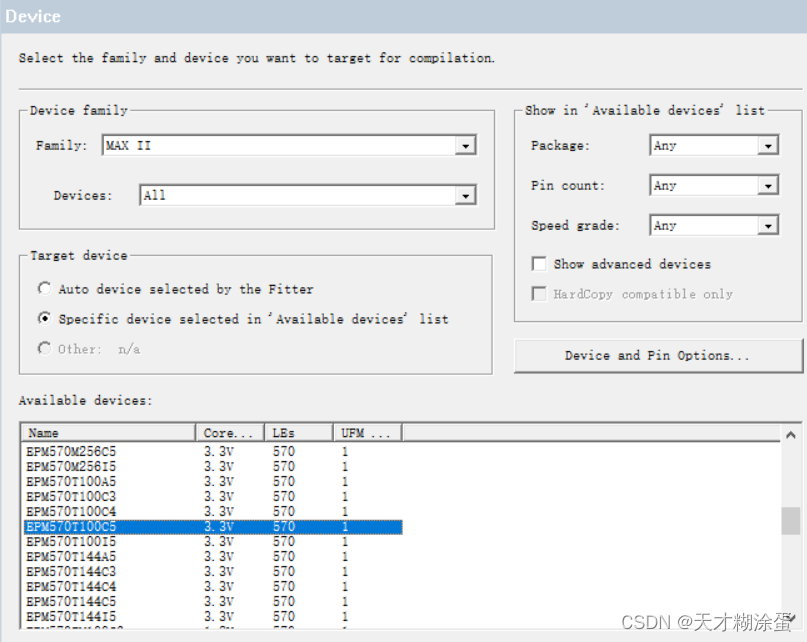
第四步:在family栏选择芯片型号-Cyclone IV E,在Name栏选择EP4CE115F29C7,选择完之后点击next。(如果不进行硬件调试时,此处默认即可)
第五步:检查工程有没有建错,点击完成。如下图:
![[外链图片转存失败,源站可能有防盗链机制,建议将图片保存下来直接上传(img-bQ40yx2C-1589528869696)(G:\研究生\FPGA课程\笔记文档\rec\20161122122950778.png)]](https://img-blog.csdnimg.cn/20200515154833880.png?x-oss-process=image/watermark,type_ZmFuZ3poZW5naGVpdGk,shadow_10,text_aHR0cHM6Ly9ibG9nLmNzZG4ubmV0L3FxXzE3MTE5MjY3,size_16,color_FFFFFF,t_70#pic_center)
程序设计:
状态机顶层文件设计(设计风格一):
--文件名:simple_fsm.vhd 应与工程名保持一致:
library ieee;
use ieee.std_logic_1164.all;
entity simple_fsm isport ( a, b, d, rst, clk: in BIT;x: out BIT);
end simple_fsm;
architecture Fsm of  simple_fsm istype state is (stateA, stateB);signal pr_state, nx_state: state;
begin
------------lower section---------------
process (clk, rst)
beginif (rst = '1')  thenpr_state <= stateA;elsif (clk'event and clk='1') thenpr_state <= nx_state;end if;
end process;
------------upper section---------------
process ( a, b, d, pr_state)
begincase pr_state iswhen stateA=>x <=a;if (d='1') then nx_state<=stateB;else nx_state<=stateA;end if;             when  stateB=>x<=b;if (d='1') then nx_state<=stateA;else nx_state<=stateB;end if;end case;
end process;
end Fsm;
状态机顶层文件设计(设计风格二):
library ieee;
use ieee.std_logic_1164.all;
entity simple_fsm1 isport ( a, b, d, rst, clk: in BIT;x: out BIT);
end simple_fsm1;
architecture simple_fsm of  simple_fsm1 istype state is (stateA, stateB);signal pr_state, nx_state: state;signal temp: BIT;
begin
------------lower section---------------
process (clk, rst)
beginif (rst = '1')  thenpr_state <= stateA;elsif (clk'event and clk='1') thenpr_state <= nx_state;x<=temp;end if;
end process;------------upper section---------------
process ( a, b, d, pr_state)
begincase pr_state iswhen stateA=>temp<=a;if (d='1') then nx_state<=stateB;else nx_state<=stateA;end if;             when  stateB=>temp<=b;if (d='1') then nx_state<=stateA;else nx_state<=stateB;end if;end case;
end process;
end simple_fsm;
文件仿真(这里采用modelsim仿真波形):
- 选择File-> New -> Verification/Debugging Files ->University Program VWF。
![[外链图片转存失败,源站可能有防盗链机制,建议将图片保存下来直接上传(img-F4kPrYX2-1589528869700)(G:\研究生\FPGA课程\笔记文档\rec\QQ截图20200423165155.png)]](https://img-blog.csdnimg.cn/20200515154904297.png#pic_center)
2.打开测试文件。(右键点击添加端口,对输入信号初始化,赋值。)
设计风格1:

设计风格2:
![[外链图片转存失败,源站可能有防盗链机制,建议将图片保存下来直接上传(img-XgIBx05M-1589528869704)(G:\研究生\FPGA课程\笔记文档\rec\微信截图_20200515151822.png)]](https://img-blog.csdnimg.cn/20200515154958383.png?x-oss-process=image/watermark,type_ZmFuZ3poZW5naGVpdGk,shadow_10,text_aHR0cHM6Ly9ibG9nLmNzZG4ubmV0L3FxXzE3MTE5MjY3,size_16,color_FFFFFF,t_70#pic_center)
3.仿真结果:
设计风格1:
![[外链图片转存失败,源站可能有防盗链机制,建议将图片保存下来直接上传(img-SyHULjIF-1589528869705)(G:\研究生\FPGA课程\笔记文档\rec\微信截图_20200515152217.png)]](https://img-blog.csdnimg.cn/20200515155012391.png?x-oss-process=image/watermark,type_ZmFuZ3poZW5naGVpdGk,shadow_10,text_aHR0cHM6Ly9ibG9nLmNzZG4ubmV0L3FxXzE3MTE5MjY3,size_16,color_FFFFFF,t_70#pic_center)
设计风格2:
![[外链图片转存失败,源站可能有防盗链机制,建议将图片保存下来直接上传(img-m1npq3uy-1589528869707)(G:\研究生\FPGA课程\笔记文档\rec\微信截图_20200515151859.png)]](https://img-blog.csdnimg.cn/20200515155026868.png?x-oss-process=image/watermark,type_ZmFuZ3poZW5naGVpdGk,shadow_10,text_aHR0cHM6Ly9ibG9nLmNzZG4ubmV0L3FxXzE3MTE5MjY3,size_16,color_FFFFFF,t_70#pic_center)
逻辑电路图:
显示编译成功后,选择菜单栏 Tools –>Netlist Viewers –>RTL Viewer 显示逻辑电路图
设计风格1:
![[外链图片转存失败,源站可能有防盗链机制,建议将图片保存下来直接上传(img-IbvMswG3-1589528869710)(G:\研究生\FPGA课程\笔记文档\rec\微信截图_20200515154440.png)]](https://img-blog.csdnimg.cn/20200515155044818.png?x-oss-process=image/watermark,type_ZmFuZ3poZW5naGVpdGk,shadow_10,text_aHR0cHM6Ly9ibG9nLmNzZG4ubmV0L3FxXzE3MTE5MjY3,size_16,color_FFFFFF,t_70#pic_center)
设计风格2:
![[外链图片转存失败,源站可能有防盗链机制,建议将图片保存下来直接上传(img-zjZXVLqy-1589528869712)(G:\研究生\FPGA课程\笔记文档\rec\微信截图_20200515154527.png)]](https://img-blog.csdnimg.cn/20200515155057139.png?x-oss-process=image/watermark,type_ZmFuZ3poZW5naGVpdGk,shadow_10,text_aHR0cHM6Ly9ibG9nLmNzZG4ubmV0L3FxXzE3MTE5MjY3,size_16,color_FFFFFF,t_70#pic_center)