osgGA::CameraManipulator类computeHomePosition函数代码如下:
void CameraManipulator::computeHomePosition(const osg::Camera *camera, bool useBoundingBox)
{if (getNode()){osg::BoundingSphere boundingSphere;OSG_INFO<<" CameraManipulator::computeHomePosition("<<camera<<", "<<useBoundingBox<<")"<<std::endl;if (useBoundingBox){// compute bounding box// (bounding box computes model center more precisely than bounding sphere)osg::ComputeBoundsVisitor cbVisitor;getNode()->accept(cbVisitor);osg::BoundingBox &bb = cbVisitor.getBoundingBox();if (bb.valid()) boundingSphere.expandBy(bb);else boundingSphere = getNode()->getBound();}else{// compute bounding sphereboundingSphere = getNode()->getBound();}OSG_INFO<<"    boundingSphere.center() = ("<<boundingSphere.center()<<")"<<std::endl;OSG_INFO<<"    boundingSphere.radius() = "<<boundingSphere.radius()<<std::endl;// set dist to defaultdouble dist = 3.5f * boundingSphere.radius();if (camera){// try to compute dist from frustumdouble left,right,bottom,top,zNear,zFar;if (camera->getProjectionMatrixAsFrustum(left,right,bottom,top,zNear,zFar)){double vertical2 = fabs(right - left) / zNear / 2.;double horizontal2 = fabs(top - bottom) / zNear / 2.;double dim = horizontal2 < vertical2 ? horizontal2 : vertical2;double viewAngle = atan2(dim,1.);dist = boundingSphere.radius() / sin(viewAngle);}else{// try to compute dist from orthoif (camera->getProjectionMatrixAsOrtho(left,right,bottom,top,zNear,zFar)){dist = fabs(zFar - zNear) / 2.;}}}// set home positionsetHomePosition(boundingSphere.center() + osg::Vec3d(0.0,-dist,0.0f),boundingSphere.center(),osg::Vec3d(0.0f,0.0f,1.0f),_autoComputeHomePosition);}
}
这个函数用于计算操控器默认位置。该计算方法考虑了相机视场角和模型大小及相机和模型之间的距离足够远,以便能将整个模型投放到计算机屏幕上。如果第1个参数即相机对象为NULL,场景到相机之间的距离将不能被计算,这种情况下将采用默认距离。useBoundingBox参数将用场景的包围盒来代替场景的包围球,因为包围盒在用于计算场景中心时将比包围球更精确,这对某些应用程序来说,有时很重要。
这个函数中,最难理解的第39到第43行代码,下面分析:
关于osg的坐标系统有必要解释一下:OpenGL的世界坐标轴向是:x轴向右,y轴向上,z轴向屏幕外。在osg中实际上也是一样的,只不过漫游器在设置视点时把视点设置在了y轴负方向并朝向y轴正向,导致这二者看起来坐标系统不一致。 感觉像是OpenGL坐标系统沿着x轴顺时针翻转90度。并且osg提供的模型数据的顶点坐标也都遵循这一原则,最终让使用者感觉osg的坐标系统是 x轴向右,y轴向屏幕里,z轴朝上。如下为OPenGL中提到的经典的平头截体:
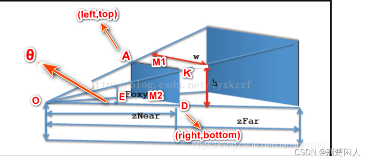 图1 平头截体
在上图中,操控器也即相机位于O点;M2点是近面和底面交线的中点(近面和底面是垂直的);M1点是近面和上顶面交线的中点;A点是近平面左上角顶点,其坐标为(left,top);D点近平面右下角顶点,其坐标为(right, bottom);E是左下角顶点,坐标为(left, bottom);OM2 = zNear(注:图中zNear标注的不对); ∠M1OM2 = Foxy为Z轴方向(垂直方向)的视场角;∠EOD = θ是水平方向视场角。
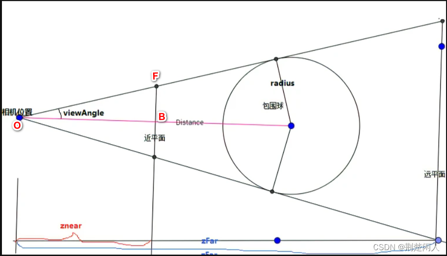
图 2
在图2中,OB线段将垂直方向的视场角等分,即2 * viewAngle = ∠M1OM2 = Foxy, 根据几何关系不难得出:
tan(viewAngle) = FB / BO = FB / zNear根据图1,FB = (top - bottom) / 2.0,则:
viewAngle = atan2( (top - bottom) / 2.0 / zNear, 1.);同样地:
tan( θ/ 2.0) = EM2 / zNear = (right - left) / 2.0 /zNear
所以:
θ / 2.0 = atan2( (right - left) / 2.0 / zNear, 1.);为了防止负数,最好加上绝对值,即:
viewAngle = atan2( fab(top - bottom) / 2.0 / zNear, 1.);θ / 2.0 = atan2( fab(right - left) / 2.0 / zNear, 1.);上述的fabs(right - left) / 2 / zNear 就是代码中的vertical2;而fab(top - bottom) / 2.0 / zNear就是代码中的horizontal2。代码中的取名是编写者把变量搞反了,应该是:
double horizontal2 = fabs(right - left) / zNear / 2.;
double vertical2 = fabs(top - bottom) / zNear / 2.;这个问题我同gitbub上osg的开发维护者robertosfield 沟通过,下面是他的回复:

沟通连接为:Should naming be exchanged? · Issue #1227 · openscenegraph/OpenSceneGraph (github.com) 。
然后再比较水平视场角和垂直视场角哪个小,以小的为场景包围球的最终视场角,这样就可以让整个场景被相机观察到,即整个场景都在平头截体内部(大角表示的视场角方向))或被平头截体内切(小角表示的视场角方向)。如果以大角为最终视场角,则当场景正好被大角所表示的平头截体内切时,则此时小的视场角(可能是水平方向的视场角,也可能是垂直方向的视场角)必定和场景包围球相交了,根据OPenGL裁剪原理,所有超出平头截体之外的场景都会被裁剪掉,从而导致部分场景不能显示在计算机屏幕上,这样用户就感觉怪怪的(我想要的场景有部分没显示在屏幕上)。
算出角度后,根据正弦就很容易算出相机离包围球中心的距离了。最后如果获取相机透视投影参数失败,那么按平行投影进行计算。平行投影的计算比较简单,去远平面和近平面差值的1/2。
参考链接:
【1】:osg中漫游器的原理——osgGA::CameraManipulator(二)。


