QEMU 与 KVM 架构
QEMU 与 KVM 的完整架构如下图所示。
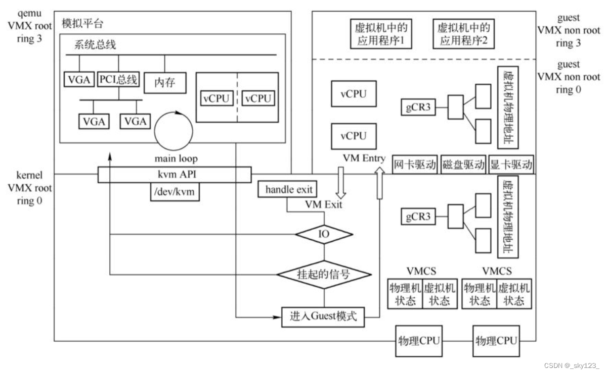
QEMU 与 KVM 架构整体上分为 3 个部分:
- VMX root 模式的应用层,即图中左上部分,属于 qemu 进程。
- VMX root 模式的内核层,即图中下半部分,属于 kvm 驱动。
- VMX non-root模式下的虚拟机,即图中右上部分,属于运行中的客户机。
其中 VMX root 和 VMX non-root 都是 CPU 引入了支持硬件虚拟化的指令集 VT-x 之后出现的概念。虚拟机在 VMX root 模式和 VMX non-root 模式下都有 ring 0 到 ring 3 四个特权级别。
图中左边上半部分列出了QEMU 的主要任务,QEMU 在初始化的时候会创建模拟的芯片组,创建 CPU 线程来表示虚拟机的 CPU 执行流,在 QEMU 的虚拟地址空间中分配空间作为虚拟机的物理地址,QEMU 还需要根据用户在命令行指定的设备为虚拟机创建对应的虚拟设备。在虚拟机运行期间,QEMU 会在主线程中监听多种事件,这些事件包括虚拟机对设备的 I/O 访问、用户对虚拟机管理界面、虚拟设备对应的宿主机上的一些 I/O 事件(比如虚拟机网络数据的接收)等。QEMU 应用层接收到这些事件之后会调用预先定义好的函数进行处理。
图中右边上半部分表示的是虚拟机的运行。对虚拟机本身来讲,它也有自己的应用层和内核层,只不过是 VMX non-root 下的。QEMU 和 KVM 对虚拟机中的操作系统来说是完全透明的,常用的操作系统可以不经修改就直接运行在虚拟机中。虚拟机的一个 CPU 对应为 QEMU 进程中的一个线程,通过 QEMU 和 KVM 的相互协作,这些线程会被宿主机操作系统正常调度,直接执行虚拟机中的代码。虚拟机中的物理内存对应为 QEMU 进程中的虚拟内存,虚拟机中的操作系统有自己的页表管理,完成虚拟机虚拟地址到虚拟机物理地址的转换,再经过 KVM 的页表完成虚拟机物理地址到宿主机物理地址的转换。虚拟机中的设备是通过 QEMU 呈现给它的,操作系统在启动的时候进行设备枚举,加载对应的驱动。在运行过程中,虚拟机操作系统通过设备的 I/O 端口(Port IO、PIO)或者 MMIO(Memory Mapped I/O)进行交互,KVM 会截获这个请求,大多数时候 KVM 会将请求分发到用户空间的 QEMU 进程中,由 QEMU 处理这些 I/O 请求。
图中下半部分表示的是位于 Linux 内核中的 KVM 驱动。 KVM 驱动以杂项(misc)设备驱动的方式存在于内核中。一方面,KVM 通过 /dev/kvm 设备导出了一系列的接口,QEMU 等用户态程序可以通过这些接口来控制虚拟机的各个方面,比如 CPU 个数、内存布局、运行等。另一方面,KVM 需要截获虚拟机产生的虚拟机退出(VM Exit)事件并进行处理。
QEMU 虚拟化
CPU 虚拟化
QEMU创建虚拟机CPU线程,在初始化的时候会设置好相应的虚拟CPU寄存器的值,然后调用KVM的接口,将虚拟机运行起来,在物理CPU上执行虚拟机的代码。当虚拟机运行起来之后,KVM需要截获虚拟机中的敏感指令,当虚拟机中的代码是敏感指令或者说满足了一定的退出条件时,CPU会从VMX non-root模式退出到KVM,这叫作VM Exit,这就像在用户态执行指令陷入内核一样。虚拟机的退出首先陷入到KVM中进行处理,如果KVM无法处理,比如说虚拟机写了设备的寄存器地址,那么KVM会将这个写操作分派到QEMU中进行处理,当KVM或者QEMU处理好了退出事件之后,又可以将CPU置于VMX non-root模式运行虚拟机代码,这叫作VM Entry。虚拟机就这样不停地进行VM Exit和VM Entry,CPU会加载对应的宿主机状态或者虚拟机状态。KVM使用一个结构来保存虚拟机VM Exit和VM Entry的状态,叫作VMCS。
内存虚拟化
如同物理机运行需要内存一样,虚拟机的运行同样离不开内存,QEMU在初始化的时候需要调用KVM的接口向KVM告知虚拟机所需要的所有物理内存。QEMU在初始化的时候会通过mmap系统调用分配虚拟内存空间作为虚拟机的物理内存,QEMU在不断更新内存布局的过程中会持续调用KVM接口通知内核KVM模块虚拟机的内存分布。虚拟机在运行过程中,首先需要将虚拟机的虚拟地址(Guest Virtual Address,GVA)转换成虚拟机的物理地址(Guest Physical Address,GPA),然后将虚拟机的物理地址转换成宿主机的虚拟地址(Host Virtual Address,HVA),最终转换成宿主机的物理地址(Host Physical Address,HPA)。
                        Guest' processes+--------------------+
Virtual addr space   |                    |+--------------------+|                    |\__   Page Table     \__\                    \|                    |  Guest kernel+----+--------------------+----------------+
Guest's phy. memory |    |                    |                |+----+--------------------+----------------+|                                          |\__                                        \__\                                          \|             QEMU process                 |+----+------------------------------------------+
Virtual addr space |    |                                          |+----+------------------------------------------+|                                               |\__                Page Table                   \__\                                               \|                                               |+----+-----------------------------------------------++
Physical memory    |    |                                               ||+----+-----------------------------------------------++
外设虚拟化
设备模拟的本质是要为虚拟机提供一个与物理设备接口完全一致的虚拟接口。虚拟机中的操作系统与设备进行的数据交互或者由QEMU和(或)KVM完成,或者由宿主机上对应的后端设备完成。QEMU在初始化过程中会创建好模拟芯片组和必要的模拟设备,包括南北桥芯片、PCI根总线、ISA根总线等总线系统,以及各种PCI设备、ISA设备等。QEMU的命令行可以指定可选的设备以及设备配置项。
中断虚拟化
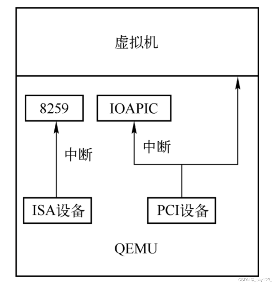
QEMU在初始化主板芯片的时候初始化中断控制器。QEMU支持单CPU的Intel 8259中断控制器以及SMP的I/O APIC(I/O Advanced Programmable Interrupt Controller)和LAPIC(Local Advanced Programmable Interrupt Controller)中断控制器。传统上,如果虚拟外设通过QEMU向虚拟机注入中断,需要先陷入到KVM,然后由KVM向虚拟机注入中断,这是一个非常费时的操作,为了提高虚拟机的效率,KVM自己也实现了中断控制器Intel 8259、I/O APIC以及LAPIC。用户可以有选择地让QEMU或者KVM模拟全部中断控制器,也可以让QEMU模拟Intel 8259中断控制器和I/O APIC,让KVM模拟LAPIC。QEMU/KVM一方面需要完成这项中断设备的模拟,另一方面需要模拟中断的请求。中断请求的形式大体上包括传统ISA设备连接Intel 8259中断控制器产生的中断请求,PCI设备的INTx中断请求以及MSI和MSIX中断请求。
PCI 设备
基本概念
PCI 即 Peripheral Component Interconnect,是一种连接电脑主板和外部设备的总线标准,其通过多根 PCI bus 完成 CPU 与 多个 PCI 设备间的连接,在 X86 硬件体系结构中几乎所有的设备都以各种形式连接到 PCI 设备树上。
每一个PCI设备在系统中的位置由总线号(Bus Number),设备号(Device Number)以及功能号(Function Number)唯一确定。在 Linux 下我们可以使用 lspci 指令查看插在当前机器的 PCI bus 上的 PCI 设备,使用 -t 参数查看树形结构,-v 参数可以查看详细信息,其中每个设备开头都可以看到形如 xx:yy.z 的十六进制编号,这个格式其实是 总线编号:设备编号.功能编号 。
➜  ~ lspci
00:00.0 Host bridge: Intel Corporation 440BX/ZX/DX - 82443BX/ZX/DX Host bridge (rev 01)
00:01.0 PCI bridge: Intel Corporation 440BX/ZX/DX - 82443BX/ZX/DX AGP bridge (rev 01)
00:07.0 ISA bridge: Intel Corporation 82371AB/EB/MB PIIX4 ISA (rev 08)
00:07.1 IDE interface: Intel Corporation 82371AB/EB/MB PIIX4 IDE (rev 01)
00:07.3 Bridge: Intel Corporation 82371AB/EB/MB PIIX4 ACPI (rev 08)
00:07.7 System peripheral: VMware Virtual Machine Communication Interface (rev 10)
00:0f.0 VGA compatible controller: VMware SVGA II Adapter
00:10.0 SCSI storage controller: LSI Logic / Symbios Logic 53c1030 PCI-X Fusion-MPT Dual Ultra320 SCSI (rev 01)
00:11.0 PCI bridge: VMware PCI bridge (rev 02)
00:15.0 PCI bridge: VMware PCI Express Root Port (rev 01)
00:15.1 PCI bridge: VMware PCI Express Root Port (rev 01)
00:15.2 PCI bridge: VMware PCI Express Root Port (rev 01)
00:15.3 PCI bridge: VMware PCI Express Root Port (rev 01)
00:15.4 PCI bridge: VMware PCI Express Root Port (rev 01)
00:15.5 PCI bridge: VMware PCI Express Root Port (rev 01)
00:15.6 PCI bridge: VMware PCI Express Root Port (rev 01)
00:15.7 PCI bridge: VMware PCI Express Root Port (rev 01)
00:16.0 PCI bridge: VMware PCI Express Root Port (rev 01)
00:16.1 PCI bridge: VMware PCI Express Root Port (rev 01)
00:16.2 PCI bridge: VMware PCI Express Root Port (rev 01)
00:16.3 PCI bridge: VMware PCI Express Root Port (rev 01)
00:16.4 PCI bridge: VMware PCI Express Root Port (rev 01)
00:16.5 PCI bridge: VMware PCI Express Root Port (rev 01)
00:16.6 PCI bridge: VMware PCI Express Root Port (rev 01)
00:16.7 PCI bridge: VMware PCI Express Root Port (rev 01)
00:17.0 PCI bridge: VMware PCI Express Root Port (rev 01)
00:17.1 PCI bridge: VMware PCI Express Root Port (rev 01)
00:17.2 PCI bridge: VMware PCI Express Root Port (rev 01)
00:17.3 PCI bridge: VMware PCI Express Root Port (rev 01)
00:17.4 PCI bridge: VMware PCI Express Root Port (rev 01)
00:17.5 PCI bridge: VMware PCI Express Root Port (rev 01)
00:17.6 PCI bridge: VMware PCI Express Root Port (rev 01)
00:17.7 PCI bridge: VMware PCI Express Root Port (rev 01)
00:18.0 PCI bridge: VMware PCI Express Root Port (rev 01)
00:18.1 PCI bridge: VMware PCI Express Root Port (rev 01)
00:18.2 PCI bridge: VMware PCI Express Root Port (rev 01)
00:18.3 PCI bridge: VMware PCI Express Root Port (rev 01)
00:18.4 PCI bridge: VMware PCI Express Root Port (rev 01)
00:18.5 PCI bridge: VMware PCI Express Root Port (rev 01)
00:18.6 PCI bridge: VMware PCI Express Root Port (rev 01)
00:18.7 PCI bridge: VMware PCI Express Root Port (rev 01)
02:00.0 USB controller: VMware USB1.1 UHCI Controller
02:01.0 Ethernet controller: Intel Corporation 82545EM Gigabit Ethernet Controller (Copper) (rev 01)
02:02.0 Multimedia audio controller: Ensoniq ES1371/ES1373 / Creative Labs CT2518 (rev 02)
02:03.0 USB controller: VMware USB2 EHCI Controller
02:04.0 SATA controller: VMware SATA AHCI controller
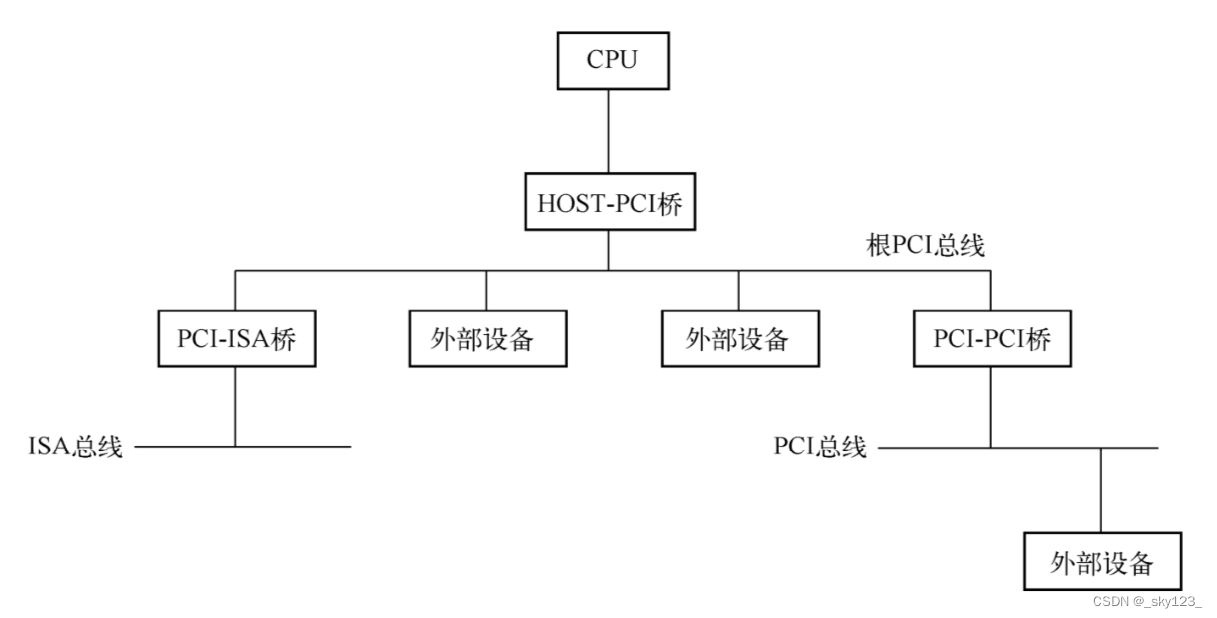
有的设备可能有多个功能,从逻辑上来说是单独的设备。可以在PCI总线上挂一个桥设备,之后在该桥上再挂一个PCI总线或者其他总线。PCI设备结构如下图所示。
配置空间
PCI设备有自己独立的地址空间,叫作PCI地址空间,也就是说从设备角度看到的地址跟CPU角度看到的地址本质上不在一个地址空间,这种隔离就是由图中的HOST-PCI主桥完成的。CPU需要通过主桥才能访问PCI设备,而PCI设备也需要通过主桥才能访问主存储器。主桥的一个重要作用就是将处理器访问的存储器地址转换为PCI总线地址。x86架构对于存储器地址空间和PCI地址空间不是很清晰,因为本质上是两个不同的地址空间,但是其地址是相同且一一对应的。
每个PCI设备都有一个配置空间,该空间至少有256字节,其中前面64个字节是标准化的,每个设备都是这个格式,后面的数据则由设备决定。
PCI 设备分为 Bridge 与 Agent 两种类型,其中 Bridge 类型是 PCI 桥,我们不做讨论,Agent 类型配置空间如下:

几个比较重要的字段:
- 设备标识相关:
- Vendor ID:生产厂商的 ID,例如 Intel 设备通常为 0x8086 。
- Device ID:具体设备的 ID,通常也是由厂家自行指定的。
- Class Code:类代码,用于区分设备类型。
- Revision ID:PCI 设备的版本号,可以看作 Device ID 的扩展。
- 设备状态相关:
- Status:设备的状态字寄存器,各 bit 含义如下图所示:

- Command:设备的状态字寄存器,各 bit 含义如下图所示:

- Status:设备的状态字寄存器,各 bit 含义如下图所示:
- 设备配置相关:
- Base Address Registers:决定了 PCI 设备空间映射到系统空间的具体位置,有两种映射方式:MMIO 与 PMIO,映射方式由最低位决定,不可更改。
- Interrupt Pin:中断引脚,该寄存器表示设备所连接的引脚。
- Interrupt Line:中断编号。
在 lspci 命令的基础上,我们可以使用 -s 来通过指定查看的具体 PCI 设备,通过 -m 查看部分信息,通过 -nn 查看比较详细的信息,另外我们还可以直接使用 -x 参数来查看 PCI 设备的配置空间。
➜  ~ lspci -vv -s 00:07.1 -nn
00:07.1 IDE interface [0101]: Intel Corporation 82371AB/EB/MB PIIX4 IDE [8086:7111] (rev 01) (prog-if 8a [ISA Compatibility mode controller, supports both channels switched to PCI native mode, supports bus mastering])Subsystem: VMware Virtual Machine Chipset [15ad:1976]Control: I/O+ Mem- BusMaster+ SpecCycle- MemWINV- VGASnoop- ParErr- Stepping- SERR- FastB2B- DisINTx-Status: Cap- 66MHz- UDF- FastB2B+ ParErr- DEVSEL=medium >TAbort- <TAbort- <MAbort- >SERR- <PERR- INTx-Latency: 64Region 0: [virtual] Memory at 000001f0 (32-bit, non-prefetchable) [size=8]Region 1: [virtual] Memory at 000003f0 (type 3, non-prefetchable)Region 2: [virtual] Memory at 00000170 (32-bit, non-prefetchable) [size=8]Region 3: [virtual] Memory at 00000370 (type 3, non-prefetchable)Region 4: I/O ports at 1060 [size=16]Kernel driver in use: ata_piixKernel modules: pata_acpi➜  ~ lspci -vv -s 00:07.1 -m
Device:	00:07.1
Class:	IDE interface
Vendor:	Intel Corporation
Device:	82371AB/EB/MB PIIX4 IDE
SVendor:	VMware
SDevice:	Virtual Machine Chipset
Rev:	01
ProgIf:	8a➜  ~ lspci -s 00:07.1 -x
00:07.1 IDE interface: Intel Corporation 82371AB/EB/MB PIIX4 IDE (rev 01)
00: 86 80 11 71 05 00 80 02 01 8a 01 01 00 40 00 00
10: 00 00 00 00 00 00 00 00 00 00 00 00 00 00 00 00
20: 61 10 00 00 00 00 00 00 00 00 00 00 ad 15 76 19
30: 00 00 00 00 00 00 00 00 00 00 00 00 ff 00 00 00
在 Linux 当中我们也可以通过 procfs 或 sysfs 这样的文件系统来查看设备的相关配置信息,例如通过 /proc/bus/pci/00/07.1` 文件我们同样可以查看 PCI 设备 00:02.0 的配置空间:
➜  ~ cat /proc/bus/pci/00/07.1 | xxd
00000000: 8680 1171 0500 8002 018a 0101 0040 0000  ...q.........@..
00000010: 0000 0000 0000 0000 0000 0000 0000 0000  ................
00000020: 6110 0000 0000 0000 0000 0000 ad15 7619  a.............v.
00000030: 0000 0000 0000 0000 0000 0000 ff00 0000  ................
通过 /sys/devices/pci0000:00/0000:00:07.1/resource 获取到的信息中每行表示一个地址空间,其中第一行为 MMIO,第二行为 PMIO,三列信息分别为起始地址、终止地址、标志位 :
➜  ~ sudo cat /sys/devices/pci0000:00/0000:00:07.1/resource
0x00000000000001f0 0x00000000000001f7 0x0000000000000110
0x00000000000003f6 0x00000000000003f6 0x0000000000000110
0x0000000000000170 0x0000000000000177 0x0000000000000110
0x0000000000000376 0x0000000000000376 0x0000000000000110
0x0000000000001060 0x000000000000106f 0x0000000000040101
0x0000000000000000 0x0000000000000000 0x0000000000000000
0x0000000000000000 0x0000000000000000 0x0000000000000000
0x0000000000000000 0x0000000000000000 0x0000000000000000
0x0000000000000000 0x0000000000000000 0x0000000000000000
0x0000000000000000 0x0000000000000000 0x0000000000000000
0x0000000000000000 0x0000000000000000 0x0000000000000000
0x0000000000000000 0x0000000000000000 0x0000000000000000
0x0000000000000000 0x0000000000000000 0x0000000000000000
PCI Base Address register
基本概念
Base Address register(BAR)是 PCI 设备配置空间中非常重要的一部分,该组寄存器(也称之为 BAR空间)用以定义 PCI 需要的配置空间大小以及配置 PCI 设备占用的地址空间
我们都知道与设备通信有两种方式:MMIO 与 Port IO,相应地 BAR 的格式也有如下两种:
- MMIO

- PMIO

BAR 的初始化
当 PCI 设备复位后,其会在 BAR 中存放该设备所需使用的资源类型与大小,当操作系统对 PCI 总线进行配置时,首先会获取到 PCI 设备的 BAR 中的初始信息,之后根据该初始信息分配合理的 PCI 总线域地址,将其写回到 BAR 当中。
通过 BAR 进行资源分配的具体过程如下:
- 当 PCI 复位时,其会向 BAR 中写入资源信息,通过将低位的 bit 设置为 read only 的 0 来标识最小地址空间大小。比如说低 20 bit 都不可写,那就是说这个 bar 所需要的地址空间最小为 1MB 。
- 系统软件(例如 BIOS)通过向 BAR 写一个所有 bit 都为 1 的值来确定从哪个 bit 开始是可写的,从而获取到该 BAR 对应所需的最小地址空间,同时通过最低位来获取到 BAR 的类型,并对应为这些 BAR 空间分配地址,并将分配的地址写回 BAR 空间中。
处理器域与 PCI 域间访问
需要注意的一点是,处理器使用存储器域的地址,而 BAR 寄存器存放 PCI 总线域的地址,因此处理器不能直接通过 BAR + offset 的方式访问 PCI 设备的 BAR 空间,而应当要将 PCI 总线域的地址转换为存储器域的地址。
由此,PCI BAR 中地址在存储器域中皆有着相应的映像,当处理器访问 PCI 设备的地址空间时,首先访问该设备在存储器域中的地址空间,之后通过 HOST 主桥将存储器域上地址空间转换为 PCI 总线域的地址空间,最后通过 PCI 总线将数据发送到指定的设备中。
反之亦然,当 PCI 设备需要访问存储器域的地址空间时(DMA 操作),首先需要访问该存储器地址空间所对应的 PCI 总线空间,之后通过 HOST 主桥将其转换为存储器地址空间,再由 DDR 控制器完成对存储器的读写。
PCI 设备内存 & 端口空间与访问方式
前面我们讲了 PCI 设备与特性和配置相关的配置空间,现在我们来看与 PCI 设备与实际操作相关的内存映射空间与端口映射空间。
所有 IO 设备的内存与端口空间需要被映射到对应的地址空间/端口空间中才能访问,这需要占用部分的内存地址空间与端口地址空间,即我们有两种映射外设资源的方式:
- MMIO(Memory-mapped I/O):即内存映射 IO。这种方式将 IO 设备的内存与寄存器映射到指定的内存地址空间上,此时我们便可以通过常规的访问内存的方式来直接访问到设备的寄存器与内存。
- PMIO(Port-mapped I/O):即端口映射 IO。这种方式将 IO 设备的寄存器编码到指定的端口上,我们需要通过访问端口的方式来访问设备的寄存器与内存(例如在 x86 下通过 in 与 out 这一类的指令可以读写端口)。IO 设备通过专用的针脚或者专用的总线与 CPU 连接,这与内存地址空间相独立,因此又称作 isolated I/O 。
完成映射之后通过相应的内存/端口访问到的便是 PCI 设备的内存/端口地址空间。
通过 procfs 的 /proc/iomem 我们可以查看物理地址空间的情况,其中我们便能看到各种设备所占用的地址空间
➜  ~ sudo cat /proc/iomem
00000000-00000fff : Reserved
00001000-0009e7ff : System RAM
0009e800-0009ffff : Reserved
000a0000-000bffff : PCI Bus 0000:00
000c0000-000c7fff : Video ROM
000ca000-000cafff : Adapter ROM
000cb000-000ccfff : Adapter ROM
000d0000-000d3fff : PCI Bus 0000:00
000d4000-000d7fff : PCI Bus 0000:00
000d8000-000dbfff : PCI Bus 0000:00
000dc000-000fffff : Reserved000f0000-000fffff : System ROM
00100000-bfecffff : System RAM
bfed0000-bfefefff : ACPI Tables
bfeff000-bfefffff : ACPI Non-volatile Storage
bff00000-bfffffff : System RAM
c0000000-febfffff : PCI Bus 0000:00c0008000-c000bfff : 0000:00:10.0e5b00000-e5bfffff : PCI Bus 0000:22e5c00000-e5cfffff : PCI Bus 0000:1ae5d00000-e5dfffff : PCI Bus 0000:12e5e00000-e5efffff : PCI Bus 0000:0ae5f00000-e5ffffff : PCI Bus 0000:21e6000000-e60fffff : PCI Bus 0000:19e6100000-e61fffff : PCI Bus 0000:11e6200000-e62fffff : PCI Bus 0000:09e6300000-e63fffff : PCI Bus 0000:20e6400000-e64fffff : PCI Bus 0000:18e6500000-e65fffff : PCI Bus 0000:10e6600000-e66fffff : PCI Bus 0000:08e6700000-e67fffff : PCI Bus 0000:1fe6800000-e68fffff : PCI Bus 0000:17e6900000-e69fffff : PCI Bus 0000:0fe6a00000-e6afffff : PCI Bus 0000:07e6b00000-e6bfffff : PCI Bus 0000:1ee6c00000-e6cfffff : PCI Bus 0000:16e6d00000-e6dfffff : PCI Bus 0000:0ee6e00000-e6efffff : PCI Bus 0000:06e6f00000-e6ffffff : PCI Bus 0000:1de7000000-e70fffff : PCI Bus 0000:15e7100000-e71fffff : PCI Bus 0000:0de7200000-e72fffff : PCI Bus 0000:05e7300000-e73fffff : PCI Bus 0000:1ce7400000-e74fffff : PCI Bus 0000:14e7500000-e75fffff : PCI Bus 0000:0ce7600000-e76fffff : PCI Bus 0000:04e7700000-e77fffff : PCI Bus 0000:1be7800000-e78fffff : PCI Bus 0000:13e7900000-e79fffff : PCI Bus 0000:0be7a00000-e7afffff : PCI Bus 0000:03e7b00000-e7ffffff : PCI Bus 0000:02e8000000-efffffff : 0000:00:0f.0e8000000-efffffff : vmwgfx probef0000000-f7ffffff : PCI MMCONFIG 0000 [bus 00-7f]f0000000-f7ffffff : Reservedf0000000-f7ffffff : pnp 00:06fb500000-fb5fffff : PCI Bus 0000:22fb600000-fb6fffff : PCI Bus 0000:1afb700000-fb7fffff : PCI Bus 0000:12fb800000-fb8fffff : PCI Bus 0000:0afb900000-fb9fffff : PCI Bus 0000:21fba00000-fbafffff : PCI Bus 0000:19fbb00000-fbbfffff : PCI Bus 0000:11fbc00000-fbcfffff : PCI Bus 0000:09fbd00000-fbdfffff : PCI Bus 0000:20fbe00000-fbefffff : PCI Bus 0000:18fbf00000-fbffffff : PCI Bus 0000:10fc000000-fc0fffff : PCI Bus 0000:08fc100000-fc1fffff : PCI Bus 0000:1ffc200000-fc2fffff : PCI Bus 0000:17fc300000-fc3fffff : PCI Bus 0000:0ffc400000-fc4fffff : PCI Bus 0000:07fc500000-fc5fffff : PCI Bus 0000:1efc600000-fc6fffff : PCI Bus 0000:16fc700000-fc7fffff : PCI Bus 0000:0efc800000-fc8fffff : PCI Bus 0000:06fc900000-fc9fffff : PCI Bus 0000:1dfca00000-fcafffff : PCI Bus 0000:15fcb00000-fcbfffff : PCI Bus 0000:0dfcc00000-fccfffff : PCI Bus 0000:05fcd00000-fcdfffff : PCI Bus 0000:1cfce00000-fcefffff : PCI Bus 0000:14fcf00000-fcffffff : PCI Bus 0000:0cfd000000-fd0fffff : PCI Bus 0000:04fd100000-fd1fffff : PCI Bus 0000:1bfd200000-fd2fffff : PCI Bus 0000:13fd300000-fd3fffff : PCI Bus 0000:0bfd400000-fd4fffff : PCI Bus 0000:03fd500000-fdffffff : PCI Bus 0000:02fd500000-fd50ffff : 0000:02:01.0fd510000-fd51ffff : 0000:02:04.0fd5c0000-fd5dffff : 0000:02:01.0fd5c0000-fd5dffff : e1000fd5ee000-fd5eefff : 0000:02:04.0fd5ee000-fd5eefff : ahcifd5ef000-fd5effff : 0000:02:03.0fd5ef000-fd5effff : ehci_hcdfdff0000-fdffffff : 0000:02:01.0fdff0000-fdffffff : e1000fe000000-fe7fffff : 0000:00:0f.0fe000000-fe7fffff : vmwgfx probefe800000-fe9fffff : pnp 00:06feb80000-feb9ffff : 0000:00:10.0feb80000-feb9ffff : mptfeba0000-febbffff : 0000:00:10.0feba0000-febbffff : mptfebc0000-febfffff : 0000:00:07.7
fec00000-fec0ffff : Reservedfec00000-fec003ff : IOAPIC 0
fec10000-fec10fff : dmar0
fed00000-fed003ff : HPET 0fed00000-fed003ff : pnp 00:04
fee00000-fee00fff : Local APICfee00000-fee00fff : Reserved
fffe0000-ffffffff : Reserved
100000000-63fffffff : System RAM3d2e00000-3d3c00e30 : Kernel code3d3c00e31-3d4a51f7f : Kernel data3d4d23000-3d51fffff : Kernel bss
通过 procfs 的 /proc/ioports 我们可以查看 IO 端口情况,其中便包括各种设备对应的 PMIO 端口:
➜  ~ sudo cat /proc/ioports
0000-0cf7 : PCI Bus 0000:000000-001f : dma10020-0021 : PNP0001:000020-0021 : pic10040-0043 : timer00050-0053 : timer10060-0060 : keyboard0061-0061 : PNP0800:000064-0064 : keyboard0070-0071 : rtc00080-008f : dma page reg00a0-00a1 : PNP0001:0000a0-00a1 : pic200c0-00df : dma200f0-00ff : fpu0170-0177 : 0000:00:07.10170-0177 : ata_piix01f0-01f7 : 0000:00:07.101f0-01f7 : ata_piix0376-0376 : 0000:00:07.10376-0376 : ata_piix03c0-03df : vga+03f6-03f6 : 0000:00:07.103f6-03f6 : ata_piix03f8-03ff : serial04d0-04d1 : PNP0001:000cf0-0cf1 : pnp 00:00
0cf8-0cff : PCI conf1
0d00-feff : PCI Bus 0000:001000-103f : 0000:00:07.31000-103f : pnp 00:001000-1003 : ACPI PM1a_EVT_BLK1004-1005 : ACPI PM1a_CNT_BLK1008-100b : ACPI PM_TMR100c-100f : ACPI GPE0_BLK1040-104f : 0000:00:07.31040-104f : pnp 00:001060-106f : 0000:00:07.11060-106f : ata_piix1070-107f : 0000:00:0f.01070-107f : vmwgfx probe1080-10bf : 0000:00:07.71080-10bf : vmw_vmci1400-14ff : 0000:00:10.02000-3fff : PCI Bus 0000:022000-203f : 0000:02:01.02000-203f : e10002040-207f : 0000:02:02.02040-207f : Ensoniq AudioPCI2080-209f : 0000:02:00.02080-209f : uhci_hcd4000-4fff : PCI Bus 0000:035000-5fff : PCI Bus 0000:0b6000-6fff : PCI Bus 0000:137000-7fff : PCI Bus 0000:1b8000-8fff : PCI Bus 0000:049000-9fff : PCI Bus 0000:0ca000-afff : PCI Bus 0000:14b000-bfff : PCI Bus 0000:1cc000-cfff : PCI Bus 0000:05d000-dfff : PCI Bus 0000:0de000-efff : PCI Bus 0000:15fce0-fcff : pnp 00:06
PCI 中断机制
PCI 设备有两种打中断的方法:传统的 INTx 中断与 MSI 中断,出于兼容的需要 PCIe 完全继承了这个特性。
INTx 中断
INTx 类型的中断即传统的通过中断引脚来产生的中断,PCI 总线使用 INTA# 、INTB# 、INTC# 、INTD# 信号(低电平有效)向处理器发出中断请求,不过多数设备仅使用 INTA# 信号 。
下图为一个产生 INTA# 中断信号的流程:
- 设备向南桥上的中断控制器打一个
INTA#,中断控制器转为 INTR 信号后通过 APIC bus 打向处理器。 - 接受中断信号的处理器(未设置则默认都打到 CPU0)通过中断向量表执行对应的处理程序。

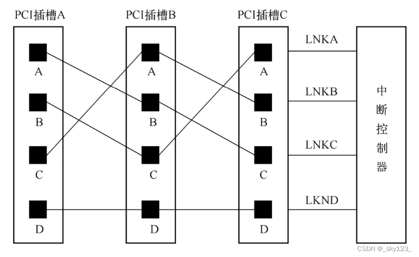
在 PCI 总线中,设备的 INTx 引脚最终要连接到中断控制器的 IRQ 引脚 ,PCI总线规范中并没有规定PCI设备的INTx信号与中断控制引脚的相连关系,因此系统软件需要使用中断路由表存放PCI设备的INTx信号与中断控制器的连接关系,中断路由表通常是由BIOS等系统软件建立的。
为了均衡PCI总线上的负载,通常PCI信号与终端信号线的连接都是错开的。如下图所示,插槽A上的设备与插槽B、C上的设备使用不同的信号线与连接中断控制器的IRQY引脚,其他类似。这种连接方式也让每个插槽的中断信号INTA连接到不同的中断设备引脚。
MSI/MSI-X 中断
Message Signaled Interrupt 是一种更为现代化与普遍的 PCI 中断机制,MSI-eXtend 则为其升级版,该机制的引入是为了消除 INTx 的边带信号,目前绝大多数 PCIe 设备已不再使用传统的 INTx 中断,而是使用 MSI/MSI-X 提交中断请求。
在 PCIe 设备中有着两个 Capability 结构,分别对应 MSI 与 MSI-X,通常一个 PCIe 设备仅会包含其中一个。对于 MSI 而言其 Capability ID 为 5,一共有四种结构,分别对应 32 位与 64 位的 Message 结构,以及对应的带上中断 Masking 的结构。

MSI/MSI-X 本质上是通过向特定的内存区域进行写入来达到中断触发的效果,当 PCI 设备提交请求时,其向 MSI/MSI-x Capability 结构中的 Message Address 地址(PCI总线域)写入 Message Data 数据,从而产生一个存储器写 TLP,由此向处理器提交存储器写请求。
MSI 仅支持 32 个连续的中断向量,而 MSI-X 支持 2048 个非连续的中断向量,但 MSI-X 的中断向量信息并不像 MSI 那样直接存放在配置空间,而是存放在 MMIO 空间中,通过BIR(Base address Indicator Register)与 BAR 来确定其在 MMIO 中的具体位置。
QEMU Object Model
QOM的全称是QEMU Object Model,该结构用来实现实现面向对象,要由这四个组件构成:
- Type:用来定义一个「类」的基本属性,例如类的名字、大小、构造函数等
- Class:用来定义一个「类」的静态内容,例如类中存储的静态数据、方法函数指针等
- Object:动态分配的一个「类」的具体的实例(instance),储存类的动态数据
- Property:动态对象数据的访问器(accessor),可以通过监视器接口进行检查
QOM 的各个组件之间关系如下图所示:

QOM整个运作包括3个部分,即类型的注册、类型的初始化以及对象的初始化。
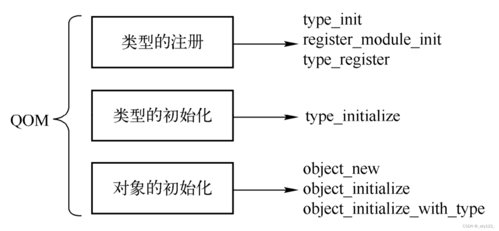
类型的注册
TypeInfo 这一结构体用来定义一个「类」的基本属性,该结构体定义于 include/qom/object.h 当中:
/*** TypeInfo:* @name: The name of the type.* @parent: The name of the parent type.* @instance_size: The size of the object (derivative of #Object).  If*   @instance_size is 0, then the size of the object will be the size of the*   parent object.* @instance_init: This function is called to initialize an object.  The parent*   class will have already been initialized so the type is only responsible*   for initializing its own members.* @instance_post_init: This function is called to finish initialization of*   an object, after all @instance_init functions were called.* @instance_finalize: This function is called during object destruction.  This*   is called before the parent @instance_finalize function has been called.*   An object should only free the members that are unique to its type in this*   function.* @abstract: If this field is true, then the class is considered abstract and*   cannot be directly instantiated.* @class_size: The size of the class object (derivative of #ObjectClass)*   for this object.  If @class_size is 0, then the size of the class will be*   assumed to be the size of the parent class.  This allows a type to avoid*   implementing an explicit class type if they are not adding additional*   virtual functions.* @class_init: This function is called after all parent class initialization*   has occurred to allow a class to set its default virtual method pointers.*   This is also the function to use to override virtual methods from a parent*   class.* @class_base_init: This function is called for all base classes after all*   parent class initialization has occurred, but before the class itself*   is initialized.  This is the function to use to undo the effects of*   memcpy from the parent class to the descendants.* @class_data: Data to pass to the @class_init,*   @class_base_init. This can be useful when building dynamic*   classes.* @interfaces: The list of interfaces associated with this type.  This*   should point to a static array that's terminated with a zero filled*   element.*/
struct TypeInfo
{const char *name;const char *parent;size_t instance_size;void (*instance_init)(Object *obj);void (*instance_post_init)(Object *obj);void (*instance_finalize)(Object *obj);bool abstract;size_t class_size;void (*class_init)(ObjectClass *klass, void *data);void (*class_base_init)(ObjectClass *klass, void *data);void *class_data;InterfaceInfo *interfaces;
};
以 hw/misc/edu.c 文件为例,当我们在 Qemu 中要定义一个「类」的时候,我们实际上需要定义一个 TypeInfo 类型的变量。
static void pci_edu_register_types(void)
{static InterfaceInfo interfaces[] = {{ INTERFACE_CONVENTIONAL_PCI_DEVICE },{ },};static const TypeInfo edu_info = {.name          = TYPE_PCI_EDU_DEVICE,.parent        = TYPE_PCI_DEVICE,.instance_size = sizeof(EduState),.instance_init = edu_instance_init,.class_init    = edu_class_init,.interfaces = interfaces,};type_register_static(&edu_info);
}
type_init(pci_edu_register_types)
可以看到各个 QOM 类型最终通过函数 register_module_init 注册到了系统,其中 function 是每个类型都需要实现的初始化函数,type 表示是 MODULE_INIT_QOM 。这里的 constructor 是编译器属性,编译器会把带有这个属性的函数 do_qemu_init_ ##function 放到特殊的段中,带有这个属性的函数会早于 main 函数执行,也就是说所有的 QOM 类型注册在 main 执行之前就已经执行了。
#define module_init(function, type)                                         \
static void __attribute__((constructor)) do_qemu_init_ ## function(void)    \
{                                                                           \register_module_init(function, type);                                   \
}#define type_init(function) module_init(function, MODULE_INIT_QOM)
register_module_init 及相关函数代码如下。
void register_module_init(void (*fn)(void), module_init_type type)
{ModuleEntry *e;ModuleTypeList *l;e = g_malloc0(sizeof(*e));e->init = fn;e->type = type;l = find_type(type);QTAILQ_INSERT_TAIL(l, e, node);
}
register_module_init 函数以类型的初始化函数以及所属类型(对 QOM 类型来说是 MODULE_INIT_QOM )构建出一个 ModuleEntry ,然后插入到对应 module 所属的链表中,所有 module 的链表存放在一个 init_type_list 数组中。
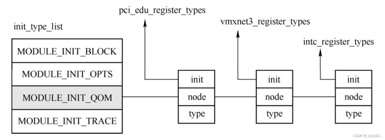
进入 main 函数后不久就以 MODULE_INIT_QOM 为参数调用了函数 module_call_init ,这个函数执行了 init_type_list[MODULE_INIT_QOM] 链表上每一个 ModuleEntry 的 init 函数。
int main(int argc, char **argv, char **envp)qemu_init(argc, argv, envp);module_call_init(MODULE_INIT_QOM);
void module_call_init(module_init_type type)
{ModuleTypeList *l;ModuleEntry *e;if (modules_init_done[type]) {return;}l = find_type(type);QTAILQ_FOREACH(e, l, node) {e->init();}modules_init_done[type] = true;
}
以 edu 设备为例,该类型的 init 函数是 pci_edu_register_types ,该函数唯一的工作是构造了一个 TypeInfo 类型的 edu_info ,并将其作为参数调用 type_register_static ,type_register_static 调用 type_register ,最终到达了 type_register_internal ,核心工作在这一函数中进行。
type_register_internal 函数很简单,type_new 函数首先通过一个 TypeInfo 结构构造出一个 TypeImpl ,type_table_add 则将这个 TypeImpl 加入到一个哈希表中。这个哈希表的 key 是 TypeImpl 的名字,value 为 TypeImpl 本身的值。
static TypeImpl *type_new(const TypeInfo *info)
{TypeImpl *ti = g_malloc0(sizeof(*ti));int i;g_assert(info->name != NULL);if (type_table_lookup(info->name) != NULL) {fprintf(stderr, "Registering `%s' which already exists\n", info->name);abort();}ti->name = g_strdup(info->name);ti->parent = g_strdup(info->parent);ti->class_size = info->class_size;ti->instance_size = info->instance_size;ti->class_init = info->class_init;ti->class_base_init = info->class_base_init;ti->class_data = info->class_data;ti->instance_init = info->instance_init;ti->instance_post_init = info->instance_post_init;ti->instance_finalize = info->instance_finalize;ti->abstract = info->abstract;for (i = 0; info->interfaces && info->interfaces[i].type; i++) {ti->interfaces[i].typename = g_strdup(info->interfaces[i].type);}ti->num_interfaces = i;return ti;
}static GHashTable *type_table_get(void)
{static GHashTable *type_table;if (type_table == NULL) {type_table = g_hash_table_new(g_str_hash, g_str_equal);}return type_table;
}static void type_table_add(TypeImpl *ti)
{assert(!enumerating_types);g_hash_table_insert(type_table_get(), (void *)ti->name, ti);
}static TypeImpl *type_register_internal(const TypeInfo *info)
{TypeImpl *ti;ti = type_new(info);type_table_add(ti);return ti;
}
TypeImpl 中存放了类型的所有信息,其定义如下。
struct TypeImpl
{const char *name;size_t class_size;size_t instance_size;void (*class_init)(ObjectClass *klass, void *data);void (*class_base_init)(ObjectClass *klass, void *data);void *class_data;void (*instance_init)(Object *obj);void (*instance_post_init)(Object *obj);void (*instance_finalize)(Object *obj);bool abstract;const char *parent;TypeImpl *parent_type;ObjectClass *class;int num_interfaces;InterfaceImpl interfaces[MAX_INTERFACES];
};
其中 name 表示类型名字,比如 edu ,isa-i8259 等; class_size ,instance_size 表示所属类的大小以及该类所属实例的大小;class_init ,class_base_init ,class_finalize 表示类相关的初始化与销毁函数,这类函数只会在类初始化的时候进行调用;instance_init, instance_post_init,instance_finalize 表示该类所属实例相关的初始化与销毁函数;abstract 表示类型是否是抽象的,与 C++ 中的 abstract 类型类似,抽象类型不能直接创建实例,只能创建其子类所属实例;parent 和 parent_type 表示父类型的名字和对应的类型信息, parent_type 是一个 TypeImpl ;class 是一个指向 ObjectClass 的指针,保存了该类型的基本信息; num_interfaces 和 interfaces 描述的是类型的接口信息,与 Java 语言中的接口类似,接口是一类特殊的抽象类型。
类型的初始化
类的初始化是通过 type_initialize 函数完成的,这个函数并不长,函数的输入是表示类型信息的 TypeImpl 类型 ti 。
函数首先判断了 ti->class 是否存在,如果不为空就表示这个类型已经初始化过了,直接返回。
if (ti->class) {return;}
后面主要做了三件事。
第一件事是设置相关的 filed ,比如 class_size 和 instance_size ,使用 ti->class_size 分配一个 ObjectClass 。
ti->class_size = type_class_get_size(ti);ti->instance_size = type_object_get_size(ti);/* Any type with zero instance_size is implicitly abstract.* This means interface types are all abstract.*/if (ti->instance_size == 0) {ti->abstract = true;}if (type_is_ancestor(ti, type_interface)) {assert(ti->instance_size == 0);assert(ti->abstract);assert(!ti->instance_init);assert(!ti->instance_post_init);assert(!ti->instance_finalize);assert(!ti->num_interfaces);}ti->class = g_malloc0(ti->class_size);
第二件事就是初始化所有父类类型,不仅包括实际的类型,也包括接口这种抽象类型。
parent = type_get_parent(ti);if (parent) {type_initialize(parent);GSList *e;int i;g_assert(parent->class_size <= ti->class_size);g_assert(parent->instance_size <= ti->instance_size);memcpy(ti->class, parent->class, parent->class_size);ti->class->interfaces = NULL;ti->class->properties = g_hash_table_new_full(g_str_hash, g_str_equal, NULL, object_property_free);for (e = parent->class->interfaces; e; e = e->next) {InterfaceClass *iface = e->data;ObjectClass *klass = OBJECT_CLASS(iface);type_initialize_interface(ti, iface->interface_type, klass->type);}for (i = 0; i < ti->num_interfaces; i++) {TypeImpl *t = type_get_by_name(ti->interfaces[i].typename);if (!t) {error_report("missing interface '%s' for object '%s'",ti->interfaces[i].typename, parent->name);abort();}for (e = ti->class->interfaces; e; e = e->next) {TypeImpl *target_type = OBJECT_CLASS(e->data)->type;if (type_is_ancestor(target_type, t)) {break;}}if (e) {continue;}type_initialize_interface(ti, t, t);}} else {ti->class->properties = g_hash_table_new_full(g_str_hash, g_str_equal, NULL, object_property_free);}ti->class->type = ti;
第三件事就是依次调用所有父类的 class_base_init 以及自己的 class_init ,这也和 C++ 很类似,在初始化一个对象的时候会依次调用所有父类的构造函数。这里是调用了父类型的 class_base_init 函数。
while (parent) {if (parent->class_base_init) {parent->class_base_init(ti->class, ti->class_data);}parent = type_get_parent(parent);}if (ti->class_init) {ti->class_init(ti->class, ti->class_data);}
实际上 type_initialize 函数可以在很多地方调用,不过,只有在第一次调用的时候会进行初始化,之后的调用会由于 ti->class 不为空而直接返回。
下面以其中一条路径来看 type_initialize 函数的调用过程。假设在启动 QEMU 虚拟机的时候不指定 machine 参数,那 QEMU 会在 main 函数中调用 select_machine ,进而由 find_default_machine 函数来找默认的 machine 类型。在那个函数之前,会调用 object_class_get_list 来得到所有 TYPE_MACHINE 类型组成的链表。
int main(int argc, char **argv, char **envp)> machine_class = select_machine();> GSList *machines = object_class_get_list(TYPE_MACHINE, false);> MachineClass *machine_class = find_default_machine(machines);
object_class_get_list 会调用 object_class_foreach ,后者会对 type_table 中所有类型调用 object_class_foreach_tramp 函数,在该函数中会调用 type_initialize 函数。
static void object_class_foreach_tramp(gpointer key, gpointer value,gpointer opaque)
{OCFData *data = opaque;TypeImpl *type = value;ObjectClass *k;type_initialize(type);k = type->class;if (!data->include_abstract && type->abstract) {return;}if (data->implements_type && !object_class_dynamic_cast(k, data->implements_type)) {return;}data->fn(k, data->opaque);
}void object_class_foreach(void (*fn)(ObjectClass *klass, void *opaque),const char *implements_type, bool include_abstract,void *opaque)
{OCFData data = { fn, implements_type, include_abstract, opaque };enumerating_types = true;g_hash_table_foreach(type_table_get(), object_class_foreach_tramp, &data);enumerating_types = false;
}GSList *object_class_get_list(const char *implements_type,bool include_abstract)
{GSList *list = NULL;object_class_foreach(object_class_get_list_tramp,implements_type, include_abstract, &list);return list;
}
类型的层次结构
在 edu 设备的类型信息 edu_info 结构中有一个 parent 成员,这就指定了 edu_info 的父类型的名称,通过分析源码可知继承关系为 TYPE_PCI_DEVICE->TYPE_DEVICE->TYPE_OBJECT 。总体上,QEMU 使用的类型一起构成了以 TYPE_OBJECT 为根的树。
在类型的初始化函数 type_initialize 中会调用 ti->class=g_malloc0(ti->class_size) 语句来分配类型的 class 结构,这个结构实际上代表了类型的信息。类似于 C++ 定义的一个类,从前面的分析看到 ti->class_size 为 TypeImpl 中的值,如果类型本身没有定义就会使用父类型的 class_size 进行初始化。edu 设备中的类型本身没有定义,所以它的 class_size 为 TYPE_PCI_DEVICE 中定义的值,即 sizeof(PCIDeviceClass) 。
typedef struct PCIDeviceClass {DeviceClass parent_class;void (*realize)(PCIDevice *dev, Error **errp);PCIUnregisterFunc *exit;PCIConfigReadFunc *config_read;PCIConfigWriteFunc *config_write;uint16_t vendor_id;uint16_t device_id;uint8_t revision;uint16_t class_id;uint16_t subsystem_vendor_id;       /* only for header type = 0 */uint16_t subsystem_id;              /* only for header type = 0 *//** pci-to-pci bridge or normal device.* This doesn't mean pci host switch.* When card bus bridge is supported, this would be enhanced.*/bool is_bridge;/* rom bar */const char *romfile;
} PCIDeviceClass;
PCIDeviceClass 表明了类属 PCI 设备的一些信息,如表示设备商信息的 vendor_id 和设备信息 device_id 以及读取 PCI 设备配置空间的 config_read 和 config_write 函数。值得注意的是,一个域是第一个成员 DeviceClass 的结构体,这描述的是属于“设备类型”的类型所具有的一些属性。
/*** ObjectClass:** The base for all classes.  The only thing that #ObjectClass contains is an* integer type handle.*/
struct ObjectClass
{/*< private >*/Type type;GSList *interfaces;const char *object_cast_cache[OBJECT_CLASS_CAST_CACHE];const char *class_cast_cache[OBJECT_CLASS_CAST_CACHE];ObjectUnparent *unparent;GHashTable *properties;
};typedef struct DeviceClass {/*< private >*/ObjectClass parent_class;/*< public >*/...
}
DeviceClass 定义了设备类型相关的基本信息以及基本的回调函数,第一个域也是表示其父类型的 Class ,为 ObjectClass 。 ObjectClass 是所有类型的基础,会内嵌到对应的其他 Class 的第一个域中。
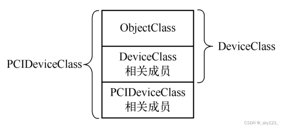
在 type_initialize 中会调用以下代码来对父类型所占的这部分空间进行初始化。
parent = type_get_parent(ti);if (parent) {...memcpy(ti->class, parent->class, parent->class_size);...}...if (ti->class_init) {ti->class_init(ti->class, ti->class_data);}
对于 edu 设备来说这里的 class_init 为 edu_class_init 。
static void edu_class_init(ObjectClass *class, void *data)
{DeviceClass *dc = DEVICE_CLASS(class);PCIDeviceClass *k = PCI_DEVICE_CLASS(class);k->realize = pci_edu_realize;k->exit = pci_edu_uninit;k->vendor_id = PCI_VENDOR_ID_QEMU;k->device_id = 0x11e8;k->revision = 0x10;k->class_id = PCI_CLASS_OTHERS;set_bit(DEVICE_CATEGORY_MISC, dc->categories);
}
类型转换 DEVICE_CLASS 和 PCI_DEVICE_CLASS 最终调用的函数为 object_class_dynamic_cast 。
函数首先通过 type_get_by_name 得到要转到的 TypeImpl ,这里的 typename 是 TYPE_PCI_DEVICE 。
ObjectClass *object_class_dynamic_cast(ObjectClass *class,const char *typename)
{ObjectClass *ret = NULL;TypeImpl *target_type;TypeImpl *type;if (!class) {return NULL;}/* A simple fast path that can trigger a lot for leaf classes.  */type = class->type;if (type->name == typename) {return class;}target_type = type_get_by_name(typename);if (!target_type) {/* target class type unknown, so fail the cast */return NULL;}if (type->class->interfaces &&type_is_ancestor(target_type, type_interface)) {int found = 0;GSList *i;for (i = class->interfaces; i; i = i->next) {ObjectClass *target_class = i->data;if (type_is_ancestor(target_class->type, target_type)) {ret = target_class;found++;}}/* The match was ambiguous, don't allow a cast */if (found > 1) {ret = NULL;}} else if (type_is_ancestor(type, target_type)) {ret = class;}return ret;
}
以 edu 为例,type->name 是 edu ,但是要转换到的却是 TYPE_PCI_DEVICE ,所以会调用 type_is_ancestor("edu",TYPE_PCI_DEVICE) 来判断后者是否是前者的祖先。
在该函数中依次得到 edu 的父类型,然后判断是否与 TYPE_PCI_DEVICE 相等,由 edu 设备的 TypeInfo 可知其父类型为 TYPE_PCI_DEVICE ,所以这个 type_is_ancestor 会成功,能够进行从 ObjectClass 到 PCIDeviceClass 的转换。这样就可以直接通过 (PCIDeviceClass*)ObjectClass 完成从 ObjectClass 到 PCIDeviceClass 的强制转换。
static TypeImpl *type_get_parent(TypeImpl *type)
{if (!type->parent_type && type->parent) {type->parent_type = type_get_by_name(type->parent);if (!type->parent_type) {fprintf(stderr, "Type '%s' is missing its parent '%s'\n",type->name, type->parent);abort();}}return type->parent_type;
}static bool type_is_ancestor(TypeImpl *type, TypeImpl *target_type)
{assert(target_type);/* Check if target_type is a direct ancestor of type */while (type) {if (type == target_type) {return true;}type = type_get_parent(type);}return false;
}
对象的构造与初始化
前面提到,首先每个类型指定一个 TypeInfo 注册到系统中,接着在系统运行初始化的时候会把 TypeInfo 转变成 TypeImple 放到一个哈希表中,这就是类型的注册。系统会对这个哈希表中的每一个类型进行初始化,主要是设置 TypeImpl 的一些域以及调用类型的 class_init 函数,这就是类型的初始化。现在系统中已经有了所有类型的信息并且这些类型的初始化函数已经调用了,接着会根据需要(如 QEMU 命令行指定的参数)创建对应的实例对象,也就是各个类型的 object 。
下面来分析指定 -device edu 命令的情况。在 main 函数中有这么一句话。
qemu_opts_foreach(qemu_find_opts("device"),device_init_func, NULL, &error_fatal);
对每一个 -device 的参数,会调用 device_init_func 函数,该函数随即调用 qdev_device_add 进行设备的添加。通过 object_new 来构造对象,其调用链如下。
device_init_func
|   dev = qdev_device_add(opts, errp);
|   |   dev = DEVICE(object_new(driver));
|   |   |   TypeImpl *ti = type_get_by_name(typename);
|   |   |   object_new_with_type(ti);
|   |   |   |   obj = g_malloc(type->instance_size);
|   |   |   |   object_initialize_with_type(obj, type->instance_size, type);
|   |   |   |   |   object_init_with_type(obj, type);
|   |   |   |   |   object_post_init_with_type(obj, type);
|   |   object_property_set_bool(OBJECT(dev), true, "realized", &err);
object_initialize_with_type 的主要工作是对 object_init_with_type 和 object_post_init_with_type 进行调用,前者通过递归调用所有父类型的对象初始化函数和自身对象的初始化函数,后者调用 TypeImpl 的 instance_post_init 回调成员完成对象初始化之后的工作。下面以 edu 的 TypeInfo 为例进行介绍。
edu 的对象大小(instance_size)为 sizeof(EduState),所以实际上一个 edu 类型的对象是 EduState 结构体,每一个对象都会有一个 XXXState 与之对应,记录了该对象的相关信息,若 edu 是一个 PCI 设备,那么 EduState 里面就会有这个设备的一些信息,如中断信息、设备状态、使用的 MMIO 和 PIO 对应的内存区域等。
在 object_init_with_type 函数中可以看到调用的参数都是一个 Object 。可以看出,对象之间实际也是有一种父对象与子对象的关系存在。与类型一样,QOM 中的对象也可以使用宏将一个指向 Object 对象的指针转换成一个指向子类对象的指针。转换过程与类型 ObjectClass 类似。
struct DeviceState {/*< private >*/Object parent_obj;/*< public >*/...
};struct DeviceState {/*< private >*/Object parent_obj;/*< public >*/...
};struct PCIDevice {DeviceState qdev;...
};typedef struct {PCIDevice pdev;...
} EduState;
这里可以看出,不同于类型信息和类型,object 是根据需要创建的,只有在命令行指定了设备或者是热插一个设备之后才会有 object 的创建。类型和对象之间是通过 Object 的 class 域联系在一起的。这是在 object_initialize_with_type 函数中通过 obj->class=type->class 实现的。
从上文可以看出,可以把 QOM 的对象构造分成 3 部分,第一部分是类型的构造,通过 TypeInfo 构造一个 TypeImpl 的哈希表,这是在 main 之前完成的;第二部分是类型的初始化,这是在 main 中进行的,这两部分都是全局的,也就是只要编译进去的 QOM 对象都会调用;第三部分是类对象的构造,这是构造具体的对象实例,只有在命令行指定了对应的设备时,才会创建对象。
现在只是构造出了对象,并且调用了对象初始化函数,但是 EduState 里面的数据内容并没有填充,这个时候的 edu 设备状态并不是可用的,对设备而言还需要设置它的 realized 属性为 true 才行。在 qdev_device_add 函数的后面,还有这样一句:
object_property_set_bool(OBJECT(dev), true, "realized", &err);
这句代码将 dev(也就是 edu 设备的 realized 属性)设置为 true ,这就涉及了 QOM 类和对象的另一个方面,即属性。
属性
在 QOM 中为了便于对对象进行管理,还给每种类型以及对象增加了属性。类属性存在于 ObjectClass 的 properties 域中,这个域是在类型初始化函数 type_initialize 中构造的。对象属性存放在 Object 的 properties 域中,这个域是在对象的初始化函数 object_initialize_with_type 中构造的。两者皆为一个哈希表,存着属性名字到 ObjectProperty 的映射。
属性由 ObjectProperty 表示。
struct ObjectProperty
{gchar *name;gchar *type;gchar *description;ObjectPropertyAccessor *get;ObjectPropertyAccessor *set;ObjectPropertyResolve *resolve;ObjectPropertyRelease *release;ObjectPropertyInit *init;void *opaque;QObject *defval;
};
其中,name 表示名字;type 表示属性的类型,如有的属性是字符串,有的是 bool 类型,有的是 link 等其他更复杂的类型;get 、set 、resolve 等回调函数则是对属性进行操作的函数;opaque 指向一个具体的属性,如 BoolProperty 等。
每一种具体的属性都会有一个结构体来描述它。比如下面的 ·LinkProperty 表示 link 类型的属性,StringProperty 表示字符串类型的属性,BoolProperty 表示 bool 类型的属性。
typedef struct {union {Object **targetp;Object *target; /* if OBJ_PROP_LINK_DIRECT, when holding the pointer  */ptrdiff_t offset; /* if OBJ_PROP_LINK_CLASS */};void (*check)(const Object *, const char *, Object *, Error **);ObjectPropertyLinkFlags flags;
} LinkProperty;typedef struct StringProperty
{char *(*get)(Object *, Error **);void (*set)(Object *, const char *, Error **);
} StringProperty;typedef struct BoolProperty
{bool (*get)(Object *, Error **);void (*set)(Object *, bool, Error **);
} BoolProperty;
以 Object 为例,属性相关结构如下:
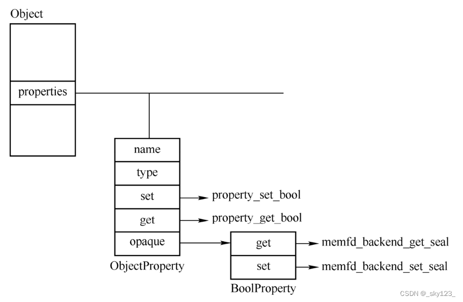
属性的添加分为类属性的添加和对象属性的添加,以对象属性为例,它的属性添加是通过 object_property_add 接口完成的。段忽略了属性 name 中带有通配符 * 的情况,该函数内容如下:
ObjectProperty *
object_property_add(Object *obj, const char *name, const char *type,ObjectPropertyAccessor *get,ObjectPropertyAccessor *set,ObjectPropertyRelease *release,void *opaque, Error **errp)
{ObjectProperty *prop;size_t name_len = strlen(name);...if (object_property_find(obj, name, NULL) != NULL) {error_setg(errp, "attempt to add duplicate property '%s' to object (type '%s')",name, object_get_typename(obj));return NULL;}prop = g_malloc0(sizeof(*prop));prop->name = g_strdup(name);prop->type = g_strdup(type);prop->get = get;prop->set = set;prop->release = release;prop->opaque = opaque;g_hash_table_insert(obj->properties, prop->name, prop);return prop;
}
object_property_add 函数首先调用 object_property_find 来确认所插入的属性是否已经存在,确保不会添加重复的属性,接着分配一个 ObjectProperty 结构并使用参数进行初始化,然后调用 g_hash_table_insert 插入到对象的 properties 域中。
属性的查找通过 object_property_find 函数实现,代码如下。
ObjectProperty *object_class_property_find(ObjectClass *klass, const char *name,Error **errp)
{ObjectProperty *prop;ObjectClass *parent_klass;parent_klass = object_class_get_parent(klass);if (parent_klass) {prop = object_class_property_find(parent_klass, name, NULL);if (prop) {return prop;}}prop = g_hash_table_lookup(klass->properties, name);if (!prop) {error_setg(errp, "Property '.%s' not found", name);}return prop;
}
这个函数首先调用 object_class_property_find 来确认自己所属的类以及所有父类都不存在这个属性,然后在自己的 properties 域中查找。
属性的设置是通过 object_property_set 来完成的,其只是简单地调用 ObjectProperty 的 set 函数。
void object_property_set(Object *obj, Visitor *v, const char *name,Error **errp)
{ObjectProperty *prop = object_property_find(obj, name, errp);if (prop == NULL) {return;}if (!prop->set) {error_setg(errp, QERR_PERMISSION_DENIED);} else {prop->set(obj, v, name, prop->opaque, errp);}
}
每一种属性类型都有自己的 set 函数,其名称为 property_set_XXX ,其中的 XXX 表示属性类型,如 bool、str、link 等。以 bool 为例,其 set 函数如下。
static void property_set_bool(Object *obj, Visitor *v, const char *name,void *opaque, Error **errp)
{BoolProperty *prop = opaque;bool value;Error *local_err = NULL;visit_type_bool(v, name, &value, &local_err);if (local_err) {error_propagate(errp, local_err);return;}prop->set(obj, value, errp);
}
可以看到,其调用了具体属性(BoolProperty)的 set 函数,这是在创建这个属性的时候指定的。
MemoryRegion - Qemu 中的一块内存区域
在 Qemu 当中使用 MemoryRegion 结构体类型来表示一块具体的 Guest 物理内存区域,该结构体定义于 include/exec/memory.h 当中:
/** MemoryRegion:** A struct representing a memory region.*/
struct MemoryRegion {Object parent_obj;/* private: *//* The following fields should fit in a cache line */bool romd_mode;bool ram;bool subpage;bool readonly; /* For RAM regions */bool nonvolatile;bool rom_device;bool flush_coalesced_mmio;bool global_locking;uint8_t dirty_log_mask;bool is_iommu;RAMBlock *ram_block;Object *owner;const MemoryRegionOps *ops;void *opaque;MemoryRegion *container;Int128 size;hwaddr addr;void (*destructor)(MemoryRegion *mr);uint64_t align;bool terminates;bool ram_device;bool enabled;bool warning_printed; /* For reservations */uint8_t vga_logging_count;MemoryRegion *alias;hwaddr alias_offset;int32_t priority;QTAILQ_HEAD(, MemoryRegion) subregions;QTAILQ_ENTRY(MemoryRegion) subregions_link;QTAILQ_HEAD(, CoalescedMemoryRange) coalesced;const char *name;unsigned ioeventfd_nb;MemoryRegionIoeventfd *ioeventfds;
};
在 Qemu 当中有三种类型的 MemoryRegion:
MemoryRegion根:通过memory_region_init()进行初始化,其用以表示与管理由多个sub-MemoryRegion组成的一个内存区域,并不实际指向一块内存区域,例如system_memoryMemoryRegion实体:通过memory_region_init_ram()初始化,表示具体的一块大小为size的内存空间,指向一块具体的内存MemoryRegion别名:通过memory_region_init_alias()初始化,作为另一个MemoryRegion实体的别名而存在,不指向一块实际内存
MR 容器与 MR 实体间构成树形结构,其中容器为根节点而实体为子节点:
                       struct MemoryRegion+------------------------+                                         |name                    |                                         |  (const char *)        |                                         +------------------------+                                         |addr                    |                                         |  (hwaddr)              |                                         |size                    |                                         |  (Int128)              |                                         +------------------------+                                         |subregions              |                                         |    QTAILQ_HEAD()       |                                         +------------------------+                                         ||----+-------------------+---------------------+----|                                         ||                                         ||                                         |struct MemoryRegion                            struct MemoryRegion
+------------------------+                     +------------------------+
|name                    |                     |name                    |
|  (const char *)        |                     |  (const char *)        |
+------------------------+                     +------------------------+
|addr                    |                     |addr                    |
|  (hwaddr)              |                     |  (hwaddr)              |
|size                    |                     |size                    |
|  (Int128)              |                     |  (Int128)              |
+------------------------+                     +------------------------+
|subregions              |                     |subregions              |
|    QTAILQ_HEAD()       |                     |    QTAILQ_HEAD()       |
+------------------------+                     +------------------------+
MemoryRegion 的成员函数被封装在函数表 MemoryRegionOps 当中:
/** Memory region callbacks*/
struct MemoryRegionOps {/* Read from the memory region. @addr is relative to @mr; @size is* in bytes. */uint64_t (*read)(void *opaque,hwaddr addr,unsigned size);/* Write to the memory region. @addr is relative to @mr; @size is* in bytes. */void (*write)(void *opaque,hwaddr addr,uint64_t data,unsigned size);MemTxResult (*read_with_attrs)(void *opaque,hwaddr addr,uint64_t *data,unsigned size,MemTxAttrs attrs);MemTxResult (*write_with_attrs)(void *opaque,hwaddr addr,uint64_t data,unsigned size,MemTxAttrs attrs);enum device_endian endianness;/* Guest-visible constraints: */struct {/* If nonzero, specify bounds on access sizes beyond which a machine* check is thrown.*/unsigned min_access_size;unsigned max_access_size;/* If true, unaligned accesses are supported.  Otherwise unaligned* accesses throw machine checks.*/bool unaligned;/** If present, and returns #false, the transaction is not accepted* by the device (and results in machine dependent behaviour such* as a machine check exception).*/bool (*accepts)(void *opaque, hwaddr addr,unsigned size, bool is_write,MemTxAttrs attrs);} valid;/* Internal implementation constraints: */struct {/* If nonzero, specifies the minimum size implemented.  Smaller sizes* will be rounded upwards and a partial result will be returned.*/unsigned min_access_size;/* If nonzero, specifies the maximum size implemented.  Larger sizes* will be done as a series of accesses with smaller sizes.*/unsigned max_access_size;/* If true, unaligned accesses are supported.  Otherwise all accesses* are converted to (possibly multiple) naturally aligned accesses.*/bool unaligned;} impl;
};
当我们的 Guest 要读写虚拟机上的内存时,在 Qemu 内部实际上会调用 address_space_rw(),对于一般的 RAM 内存而言则直接对 MR 对应的内存进行操作,对于 MMIO 而言则最终调用到对应的 MR->ops->read() 或 MR->ops->write() 。
在 Qemu 中使用 MemoryRegion 结构体来表示一段内存区域,那么我们同样可以通过在设备中添加 MemoryRegion 的方式来为设备添加内存,从而实现与设备间的 MMIO 通信。
同样的,为了统一接口,在 Qemu 当中 PMIO 的实现同样是通过 MemoryRegion 来完成的。
在自定义设备时如果想要为设备注册内存首先需要定义 MemoryRegionOps 。
static const MemoryRegionOps edu_mmio_ops = {.read = edu_mmio_read,.write = edu_mmio_write,.endianness = DEVICE_NATIVE_ENDIAN,.valid = {.min_access_size = 4,.max_access_size = 8,},.impl = {.min_access_size = 4,.max_access_size = 8,},};
然后再 edu 定义的 realize 函数中注册这块内存:
static void pci_edu_realize(PCIDevice *pdev, Error **errp)
{EduState *edu = EDU(pdev);...memory_region_init_io(&edu->mmio, OBJECT(edu), &edu_mmio_ops, edu,"edu-mmio", 1 * MiB);pci_register_bar(pdev, 0, PCI_BASE_ADDRESS_SPACE_MEMORY, &edu->mmio);
}
pci_register_bar 的第二个参数如果是 1 则注册的是 PMIO 类型的内存。
实际 QEMU 设备分析
以 HXB2019-pwn2 为例,介绍一下实际情况如何分析 QEMU 设备。
首先分析启动脚本发先在 qemu 启动时 -device 参数指定了 strng 设备。
#! /bin/sh
./qemu-system-x86_64 \
-initrd ./rootfs.cpio \
-kernel ./vmlinuz-4.8.0-52-generic \
-append 'console=ttyS0 root=/dev/ram oops=panic panic=1' \
-enable-kvm \
-monitor /dev/null \
-m 64M --nographic -L ./dependency/usr/local/share/qemu \
-L pc-bios \
-device strng
在 ida 中搜索 strng 相关函数如下:
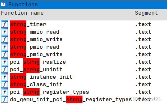
ida 分析发现 opaque 参数类型缺失导致反编译效果不理想。
void __cdecl strng_mmio_write(void *opaque, hwaddr addr, uint64_t val, unsigned int size)
{unsigned int seed; // [rsp+8h] [rbp-28h]unsigned int v5; // [rsp+24h] [rbp-Ch]seed = val;if ( size == 4 && (addr & 3) == 0 ){v5 = addr >> 2;if ( v5 == 1 ){*((_DWORD *)opaque + 703) = rand();}else if ( v5 ){if ( v5 == 3 )*((_DWORD *)opaque + 705) = rand_r((unsigned int *)opaque + 704);*((_DWORD *)opaque + 701) = 1;*((_DWORD *)opaque + v5 + 702) = seed;}else{srand(val);}}
}
参考 edu 设备的读写函数,opaque 会被强转为 EduState* 类型。
static uint64_t edu_mmio_read(void *opaque, hwaddr addr, unsigned size)
{EduState *edu = opaque;...
}
由于本题带有符号表,因此通过右键+Convert to struct* 设置为 STRNGState 类型后反编译效果明显提升。
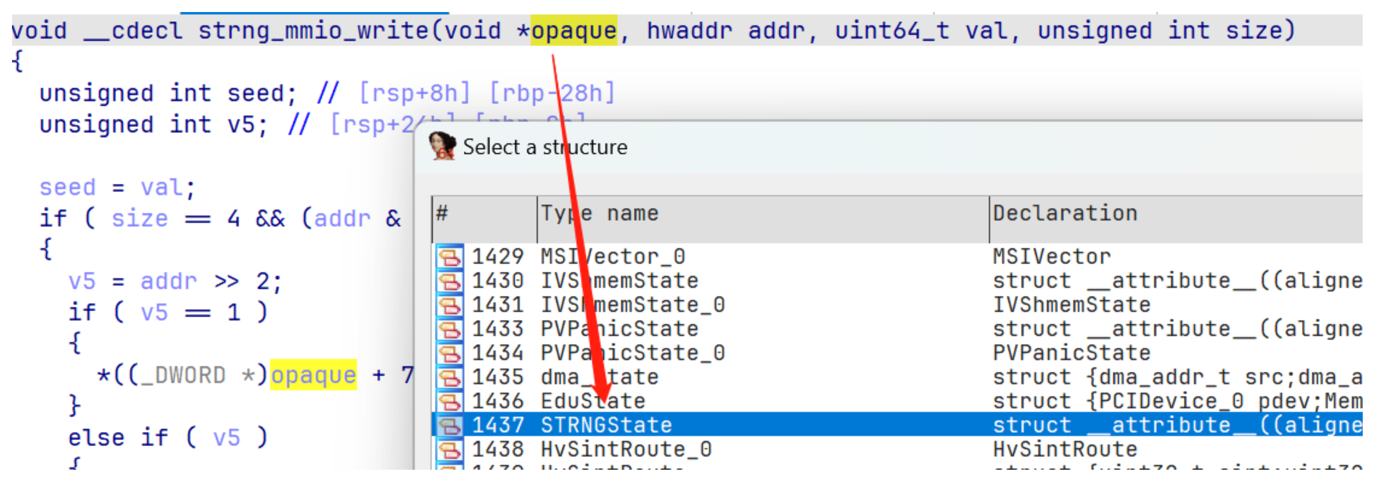
void __cdecl strng_mmio_write(STRNGState *opaque, hwaddr addr, uint64_t val, unsigned int size)
{unsigned int seed; // [rsp+8h] [rbp-28h]int v5; // [rsp+24h] [rbp-Ch]seed = val;if ( size == 4 && (addr & 3) == 0 ){v5 = addr >> 2;if ( v5 == 1 ){opaque->regs[1] = rand();}else if ( v5 ){if ( v5 == 3 )opaque->regs[3] = rand_r(&opaque->regs[2]);opaque->flag = 1;opaque->regs[v5] = seed;}else{srand(val);}}
}
QEMU 逃逸
QEMUTimers 提供了一种在经过一段时间间隔后调用给定例程回调的方法,相关函数和结构如下:
struct QEMUTimerList {QEMUTimer active_timers;
};struct QEMUTimer {int64_t expire_time;        /* in nanoseconds */QEMUTimerList *timer_list;QEMUTimerCB *cb;void *opaque;QEMUTimer *next;int attributes;int scale;
};struct QEMUTimerListGroup {QEMUTimerList *tl[QEMU_CLOCK_MAX];
}extern QEMUTimerListGroup main_loop_tlg;bool timerlist_run_timers(QEMUTimerList *timer_list)
{.../* remove timer from the list before calling the callback */timer_list->active_timers = ts->next;ts->next = NULL;ts->expire_time = -1;cb = ts->cb;opaque = ts->opaque;/* run the callback (the timer list can be modified) */qemu_mutex_unlock(&timer_list->active_timers_lock);cb(opaque);qemu_mutex_lock(&timer_list->active_timers_lock);...
}bool qemu_clock_run_all_timers(void)
{bool progress = false;QEMUClockType type;for (type = 0; type < QEMU_CLOCK_MAX; type++) {if (qemu_clock_use_for_deadline(type)) {progress |= qemu_clock_run_timers(type);}}return progress;
}bool qemu_clock_run_timers(QEMUClockType type)
{return timerlist_run_timers(main_loop_tlg.tl[type]);
}bool qemu_clock_run_all_timers(void)
{bool progress = false;QEMUClockType type;for (type = 0; type < QEMU_CLOCK_MAX; type++) {if (qemu_clock_use_for_deadline(type)) {progress |= qemu_clock_run_timers(type);}}return progress;
}void main_loop_wait(int nonblocking)
{...qemu_clock_run_all_timers();
}
因此可以在指定地址伪造 QEMUTimerList ,QEMUTimer 以及要执行的命令,然后修改 main_loop_tlg 指向伪造的 QEMUTimerList 来执行命令。


