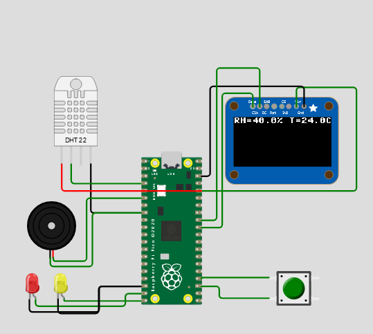
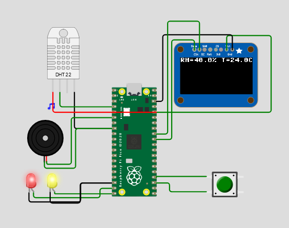
哈喽,大家好,还记得之前我们学习的使用Wokwi仿真MicroPython on ESP32开发板实现温度和湿度检测并使用屏幕显示的内容吗,这次我们加了一个按键,就是报警后可以手动取消报警。
一、目的
温湿度采集和报警,报警对应的LED灯也亮,而且报警可手动取消。
二、硬件环境

三、代码
main.py
from dt22 import DHT22
from machine import Pin, I2C,PWM
import oled
import time  pwm0 = PWM(Pin(4))
pwm0.duty_u16(32768)
pwm0.deinit()   #初始化pwm用于对蜂鸣器的控制def interruput(line):if p18.value()==1:led_red.off();led_yellow.off();pwm0.deinit();time.sleep(3)   #按键的中断函数
p18=machine.Pin(18,machine.Pin.IN,machine.Pin.PULL_UP); #初始化按键
p18.irq(trigger=machine.Pin.IRQ_RISING,handler=interruput) #按键中断DHT22 = DHT22(2)
resultList = [0, 0, 0, 0, 0]  #初始化DHT22i2c = I2C(1, scl=Pin(27), sda=Pin(26))
oled_width = 128
oled_height = 64
oled = oled.SSD1306_I2C(oled_width, oled_height, i2c) #初始化Oledled_red=Pin(14,Pin.OUT)
led_yellow=Pin(15,Pin.OUT)  #初始化ledwhile True:                   oled.fill(0)  #清屏time.sleep(3)DHT22.read_bytes(resultList)  #DHt22数据的采集HumData = ((resultList[0] << 8) + resultList[1]) / 10 #湿度TemData = ((resultList[2] << 8) + resultList[3]) / 10 #温度oled.text('RH={}% T={}C'.format(HumData,TemData), 0, 0) #数据处理   oled.show()   #显示到oledif TemData>20:  #对温度进行判断pwm0.freq(1000)led_red.on()if HumData>30: #对湿度进行判断pwm0.freq(1000)led_yellow.on()
diagram.json
{"version": 1,"author": "Anonymous maker","editor": "wokwi","parts": [{"type": "wokwi-pi-pico","id": "pico","top": 0,"left": 0,"attrs": { "env": "micropython-20220117-v1.18" }},{ "type": "wokwi-dht22", "id": "dht1", "top": -98.59, "left": -113.64, "attrs": {} },{ "type": "wokwi-ssd1306", "id": "oled1", "top": -71.05, "left": 109.69, "attrs": {} },{"type": "wokwi-buzzer","id": "bz1","top": 56.43,"left": -148.61,"attrs": { "volume": "0.1" }},{"type": "wokwi-led","id": "led1","top": 151.47,"left": -161.92,"attrs": { "color": "red" }},{"type": "wokwi-led","id": "led2","top": 150.83,"left": -124.53,"attrs": { "color": "yellow" }},{"type": "wokwi-pushbutton","id": "btn1","top": 155.62,"left": 165.22,"attrs": { "bounce": "0", "color": "green" }}],"connections": [[ "dht1:GND", "pico:GND.2", "black", [ "v0" ] ],[ "pico:3V3", "oled1:VIN", "green", [ "h202.69", "v-135.43", "h-74.67" ] ],[ "oled1:GND", "pico:GND.8", "black", [ "v-26.46", "h-122.84", "v116.67" ] ],[ "dht1:VCC", "pico:3V3", "red", [ "v0" ] ],[ "dht1:SDA", "pico:GP2", "green", [ "v0" ] ],[ "bz1:1", "pico:GND.2", "green", [ "v11.66", "h55.05", "v-67.17" ] ],[ "bz1:2", "pico:GP4", "green", [ "v4.69", "h43.45", "v-78.57" ] ],[ "led2:A", "pico:GP15", "green", [ "v0" ] ],[ "led1:A", "pico:GP14", "green", [ "v8.58", "h117.45", "v-16.48" ] ],[ "pico:GND.4", "led2:C", "black", [ "h-55.32", "v35.5", "h-51.33" ] ],[ "pico:GND.4", "led1:C", "black", [ "h-54.69", "v33.6", "h-91.25", "v2.53" ] ],[ "oled1:DATA", "pico:GP26", "green", [ "v-17.98", "h-40.03", "v180.07" ] ],[ "oled1:CLK", "pico:GP27", "green", [ "v-50.9", "h-56.23", "v10.29" ] ],[ "btn1:1.l", "pico:GP18", "green", [ "h0" ] ],[ "btn1:2.l", "pico:GND.5", "green", [ "h-64.99", "v-4.74" ] ]],"serialMonitor": { "display": "plotter", "newline": "lf" }
}
oled.py
#MicroPython SSD1306 OLED driver, I2C and SPI interfaces created by Adafruitimport time
import framebuf# register definitions
SET_CONTRAST        = const(0x81)
SET_ENTIRE_ON       = const(0xa4)
SET_NORM_INV        = const(0xa6)
SET_DISP            = const(0xae)
SET_MEM_ADDR        = const(0x20)
SET_COL_ADDR        = const(0x21)
SET_PAGE_ADDR       = const(0x22)
SET_DISP_START_LINE = const(0x40)
SET_SEG_REMAP       = const(0xa0)
SET_MUX_RATIO       = const(0xa8)
SET_COM_OUT_DIR     = const(0xc0)
SET_DISP_OFFSET     = const(0xd3)
SET_COM_PIN_CFG     = const(0xda)
SET_DISP_CLK_DIV    = const(0xd5)
SET_PRECHARGE       = const(0xd9)
SET_VCOM_DESEL      = const(0xdb)
SET_CHARGE_PUMP     = const(0x8d)class SSD1306:def __init__(self, width, height, external_vcc):self.width = widthself.height = heightself.external_vcc = external_vccself.pages = self.height // 8# Note the subclass must initialize self.framebuf to a framebuffer.# This is necessary because the underlying data buffer is different# between I2C and SPI implementations (I2C needs an extra byte).self.poweron()self.init_display()def init_display(self):for cmd in (SET_DISP | 0x00, # off# address settingSET_MEM_ADDR, 0x00, # horizontal# resolution and layoutSET_DISP_START_LINE | 0x00,SET_SEG_REMAP | 0x01, # column addr 127 mapped to SEG0SET_MUX_RATIO, self.height - 1,SET_COM_OUT_DIR | 0x08, # scan from COM[N] to COM0SET_DISP_OFFSET, 0x00,SET_COM_PIN_CFG, 0x02 if self.height == 32 else 0x12,# timing and driving schemeSET_DISP_CLK_DIV, 0x80,SET_PRECHARGE, 0x22 if self.external_vcc else 0xf1,SET_VCOM_DESEL, 0x30, # 0.83*Vcc# displaySET_CONTRAST, 0xff, # maximumSET_ENTIRE_ON, # output follows RAM contentsSET_NORM_INV, # not inverted# charge pumpSET_CHARGE_PUMP, 0x10 if self.external_vcc else 0x14,SET_DISP | 0x01): # onself.write_cmd(cmd)self.fill(0)self.show()def poweroff(self):self.write_cmd(SET_DISP | 0x00)def contrast(self, contrast):self.write_cmd(SET_CONTRAST)self.write_cmd(contrast)def invert(self, invert):self.write_cmd(SET_NORM_INV | (invert & 1))def show(self):x0 = 0x1 = self.width - 1if self.width == 64:# displays with width of 64 pixels are shifted by 32x0 += 32x1 += 32self.write_cmd(SET_COL_ADDR)self.write_cmd(x0)self.write_cmd(x1)self.write_cmd(SET_PAGE_ADDR)self.write_cmd(0)self.write_cmd(self.pages - 1)self.write_framebuf()def fill(self, col):self.framebuf.fill(col)def pixel(self, x, y, col):self.framebuf.pixel(x, y, col)def scroll(self, dx, dy):self.framebuf.scroll(dx, dy)def text(self, string, x, y, col=1):self.framebuf.text(string, x, y, col)class SSD1306_I2C(SSD1306):def __init__(self, width, height, i2c, addr=0x3c, external_vcc=False):self.i2c = i2cself.addr = addrself.temp = bytearray(2)# Add an extra byte to the data buffer to hold an I2C data/command byte# to use hardware-compatible I2C transactions.  A memoryview of the# buffer is used to mask this byte from the framebuffer operations# (without a major memory hit as memoryview doesn't copy to a separate# buffer).self.buffer = bytearray(((height // 8) * width) + 1)self.buffer[0] = 0x40  # Set first byte of data buffer to Co=0, D/C=1self.framebuf = framebuf.FrameBuffer1(memoryview(self.buffer)[1:], width, height)super().__init__(width, height, external_vcc)def write_cmd(self, cmd):self.temp[0] = 0x80 # Co=1, D/C#=0self.temp[1] = cmdself.i2c.writeto(self.addr, self.temp)def write_framebuf(self):# Blast out the frame buffer using a single I2C transaction to support# hardware I2C interfaces.self.i2c.writeto(self.addr, self.buffer)def poweron(self):passclass SSD1306_SPI(SSD1306):def __init__(self, width, height, spi, dc, res, cs, external_vcc=False):self.rate = 10 * 1024 * 1024dc.init(dc.OUT, value=0)res.init(res.OUT, value=0)cs.init(cs.OUT, value=1)self.spi = spiself.dc = dcself.res = resself.cs = csself.buffer = bytearray((height // 8) * width)self.framebuf = framebuf.FrameBuffer1(self.buffer, width, height)super().__init__(width, height, external_vcc)def write_cmd(self, cmd):self.spi.init(baudrate=self.rate, polarity=0, phase=0)self.cs.high()self.dc.low()self.cs.low()self.spi.write(bytearray([cmd]))self.cs.high()def write_framebuf(self):self.spi.init(baudrate=self.rate, polarity=0, phase=0)self.cs.high()self.dc.high()self.cs.low()self.spi.write(self.buffer)self.cs.high()def poweron(self):self.res.high()time.sleep_ms(1)self.res.low()time.sleep_ms(10)self.res.high()
dt22.py
from machine import Pin
import timeclass DHT22():def __init__(self, dht_pin):self.dht = Pin(dht_pin, Pin.OPEN_DRAIN, Pin.PULL_UP)def start(self):self.dht(0)time.sleep_ms(2)self.dht(1)while 1:if self.dht.value() == 0:breakwhile 1:if self.dht.value() == 1:breakwhile 1:if self.dht.value() == 0:breakdef read_bytes(self, dataread):byteread = 0self.start()for j in range(5):for i in range(8):while 1:if self.dht.value() == 1:breaktime.sleep_us(30)if self.dht.value():flag = 1while 1:if self.dht.value() == 0:breakelse:flag = 0byteread <<= 1byteread |= flagdataread[j] = bytereadbyteread = 0
效果:

网页展示效果,请查看如下链接:
Wokwi Arduino and ESP32 Simulator![]() https://wokwi.com/projects/341962681824051794
https://wokwi.com/projects/341962681824051794


