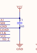
1.以下是74HC595控制数码管的电路图原理图:

封装图:

注意:2
VCC与GND 之间接滤波电容一定要遵循就近原则,如果线过长,不但起不到滤波的目的,还会将外界的杂波引入元件之中,对元件的工作造成严重影响,
stm32 的初始化程序如下(没使用定时器的程序如下):
以下是hc595.c
//初始化PA0、PA1和PA2为输出口,并使能这个端口的时钟
//HC595 IO初始化
void HC595_Init(void)
{
GPIO_InitTypeDef GPIO_InitStructure;
RCC_APB2PeriphClockCmd(RCC_APB2Periph_GPIOA, ENABLE);	 							//使能PA端口时钟GPIO_InitStructure.GPIO_Pin = GPIO_Pin_0 | GPIO_Pin_1 | GPIO_Pin_2;	//端口配置
GPIO_InitStructure.GPIO_Mode = GPIO_Mode_Out_PP; 		 								//推挽输出
GPIO_InitStructure.GPIO_Speed = GPIO_Speed_50MHz;
GPIO_Init(GPIOA, &GPIO_InitStructure);
GPIO_SetBits(GPIOA,GPIO_Pin_0 | GPIO_Pin_1 | GPIO_Pin_2);						 //PA0,1,2 输出高
}
void HC595_Display(unsigned char Bai, unsigned char Shi, unsigned char Ge)
{
uchar k;
uchar n = Ge;
uchar m = Shi;
uchar x = Bai;
for(k=0;k<8;k++)
{
if(n&0x80) HC595_SDI = 1;
else HC595_SDI = 0; //判断当前发送位数据
n <<= 1; //左移一位
HC595_CLK = 0;
//delay_ms(1);
HC595_CLK = 1; //移位寄存器操作
//delay_ms(1);
}
for(k=0;k<8;k++)
{
if(m&0x80)HC595_SDI =1;
else HC595_SDI = 0; //判断当前发送位数据
m <<= 1; //左移一位
HC595_CLK = 0;
//delay_ms(1);
HC595_CLK = 1; //移位寄存器操作
//delay_ms(1);
}
for(k=0;k<8;k++)
{if(x&0x80)HC595_SDI =1;else HC595_SDI = 0;		//判断当前发送位数据x <<= 1;							//左移一位HC595_CLK = 0;//delay_ms(1);HC595_CLK = 1;       	//移位寄存器操作//delay_ms(1);
}HC595_LE = 1;
//delay_ms(1);
HC595_LE = 0;			//锁存数据
//delay_ms(1);
}
这是main.c 中的代码
unsigned char Qian_Wei,Bai_Wei,Shi_Wei,Ge_Wei; //千位,百位,十位,个位
//数码管编码
unsigned char table[] =
{0xc0,0xf9,0xa4,0xb0,0x99,
0x92,0x82,0xf8,0x80,0x90,
0xff,0x00,0x90,0x86,0xaf,
0xc0,0x89,0xc7,0x8e,0xc1,0x7f};
//0,1,2,3,4,5,6,7,8,9,全暗,全亮,g,E,r,O,H,L,F,U,小数点,共阳数码管使用
int main(void)
{
int a, b, c, d;
a = 0;//这些常量置0,否则后面显示会出问题
b = 0;
c = 0;
d = 0;
SystemInit(); //系统时钟初始化为72M SYSCLK_FREQ_72MHz
delay_init(72); //延时函数初始化
NVIC_Configuration(); //设置NVIC中断分组2:2位抢占优先级,2位响应优先级
LED_Init(); //LED端口初始化
HC595_Init();
//清空LED数码管
Bai_Wei = table[10];//清空LED
Shi_Wei = table[10];//清空LED
Ge_Wei = table[10];//清空LED
HC595_Display(Bai_Wei, Shi_Wei,Ge_Wei);
delay_ms(3000);//依次测试百位至个位全亮
Bai_Wei = table[11];//百位全亮
Shi_Wei = table[10];//清空LED
Ge_Wei = table[10];//清空LED
HC595_Display(Bai_Wei, Shi_Wei,Ge_Wei);
delay_ms(2000);
Bai_Wei = table[10];//清空LED
Shi_Wei = table[11];//十位全亮
Ge_Wei = table[10];//清空LED
HC595_Display(Bai_Wei, Shi_Wei,Ge_Wei);
delay_ms(2000);
Bai_Wei = table[10];//清空LED
Shi_Wei = table[10];//清空LED
Ge_Wei = table[11];//个位全亮
HC595_Display(Bai_Wei, Shi_Wei,Ge_Wei);
delay_ms(2000);//同时显示0~9
Bai_Wei = table[0];
Shi_Wei = table[0];
Ge_Wei = table[0];
HC595_Display(Bai_Wei, Shi_Wei, Ge_Wei);
delay_ms(2000);
Bai_Wei = table[1];
Shi_Wei = table[1];
Ge_Wei = table[1];
HC595_Display(Bai_Wei, Shi_Wei,Ge_Wei);
delay_ms(2000);
Bai_Wei = table[2];
Shi_Wei = table[2];
Ge_Wei = table[2];
HC595_Display(Bai_Wei, Shi_Wei,Ge_Wei);
delay_ms(2000);
Bai_Wei = table[3];
Shi_Wei = table[3];
Ge_Wei = table[3];
HC595_Display(Bai_Wei, Shi_Wei,Ge_Wei);
delay_ms(2000);
Bai_Wei = table[4];
Shi_Wei = table[4];
Ge_Wei = table[4];
HC595_Display(Bai_Wei, Shi_Wei,Ge_Wei);
delay_ms(2000);
Bai_Wei = table[5];
Shi_Wei = table[5];
Ge_Wei = table[5];
HC595_Display(Bai_Wei, Shi_Wei,Ge_Wei);
delay_ms(2000);
Bai_Wei = table[6];
Shi_Wei = table[6];
Ge_Wei = table[6];
HC595_Display(Bai_Wei, Shi_Wei,Ge_Wei);
delay_ms(2000);
Bai_Wei = table[7];
Shi_Wei = table[7];
Ge_Wei = table[7];
HC595_Display(Bai_Wei, Shi_Wei,Ge_Wei);
delay_ms(2000);
Bai_Wei = table[8];
Shi_Wei = table[8];
Ge_Wei = table[8];
HC595_Display(Bai_Wei, Shi_Wei,Ge_Wei);
delay_ms(2000);
Bai_Wei = table[9];
Shi_Wei = table[9];
Ge_Wei = table[9];
HC595_Display(Bai_Wei, Shi_Wei,Ge_Wei);
delay_ms(2000);
HC595_Display(Bai_Wei, Shi_Wei,Ge_Wei);
delay_ms(2000);while(1)
{		LED0=0;							//这里使用了位带操作,也可以使用 GPIO_ResetBits(GPIOA,GPIO_Pin_8);delay_ms(20);		 LED0=1;							//也可以使用	  GPIO_SetBits(GPIOA,GPIO_Pin_8);	    		delay_ms(20);			a++;if(a==1){a = 0;b++;}if(b == 10){b = 0;c++;}if(c == 10){c = 0;d++;			}if(d == 10)d= 0;Bai_Wei = table[d];Shi_Wei = table[c];Ge_Wei = table[b];HC595_Display(Bai_Wei,Shi_Wei,Ge_Wei);//delay_ms(100);
}
}
以下为74HC595的使用电路图,初步决定使用两个74HC595进行该项目,利用8*8矩阵的方法实现目的要求。

本次制作心形流水/光立方灯采用74HC595,准备采用51单片机进行程序编写,采用三色LED灯,初步决定使用40个灯,每个灯共阴极,阳极由5组74HC595进行控制,然后每八个灯为一组,每组使用三个电阻,输入端采用三个电阻进行限流保护。如果使用数码管的画需要一个74HC573。经过对照

手头资料74HC595的电路图如下:

Q端为输出端D端为输入端
已经掌握资料的74HC595原理图与手头封装库互相对应,74HC573不是特别对应需要调整,根据资料来看,作者将74HC573的CLK和OC引脚分别接入了高低电位。使用时将左侧OUTPUT接入低电位,右侧将LAT接入了低电位。


当OE拉低电位后,不会影响锁存器的内部操作,74HC573可以正常工作,LE输入为高电平时,Q会输出响应数据,此时74HC573相当于大功率输出的IO口。
这是51系统小板和74HC573的接法了,为了提高速度,充分利用GPIO口,我直接把OE接低电平 LE接到高电平了。这样使用相当于74HC573是透明的,仅仅起驱动(放大电流)作用。
综上如果开始制作的时候可以将74HC595的原理图和74HC573的原理图进行修改,方便设计电路图。


