@[topic]ADXL345 三轴加速度角度传感器目录
ADXL345 三轴加速度角度传感器
简介
这款ADXL345三轴加速度采用ADXL345芯片,具有体积小,功耗低的特点,13位数字精度分辨能够测量超过±16g的加速度变换。信号输出为16位数字输出,可以通过SPI与I2C接口实现信号采集。ADXL345适用于倾斜角度测量,能够进行静态重力加速度检测。同时也适用于运动状态的追踪,测量运动或冲击过程造成的瞬时加速度。其高分辨率(4mg/LSB)使之能够感应变化小于1°的倾斜角度。
DFrobot的ADXL345三轴加速度计还内置一款LDO模块让你的加速度计能够工作于3.3~6v的工作电压之下。同时传感器提供了几个特殊的功能。能够在静态或动态情况下检测是否有运动或停止出现,另外能够感知单轴的加速度值是否超出用户的设定值。检测单击/双击。如果该设备正在下降,能进行自由落体感应检测。这些功能能够被映射到两个中断输出引脚上。在低功耗模式是用户能够基于ADXL345动作感应,进行电源管理,同时只损耗极低的功耗。
另外,我们提供了一些常用的三轴加速度传感器数据处理的方法:How to Use a Three-Axis Accelerometer for Tilt Sensing.
技术规格
工作电压:3.3~6v
超低功耗:测量模式下40uA电流损耗,待机模式下0.1uA@2.5v
通讯接口:I2C、SPI(3线or4线)
接口类型:0.1"插针孔
尺寸:20x15mm
应用
单击/双击检测
自由落体检测
倾角测量
切换横屏/竖屏模式
连线图
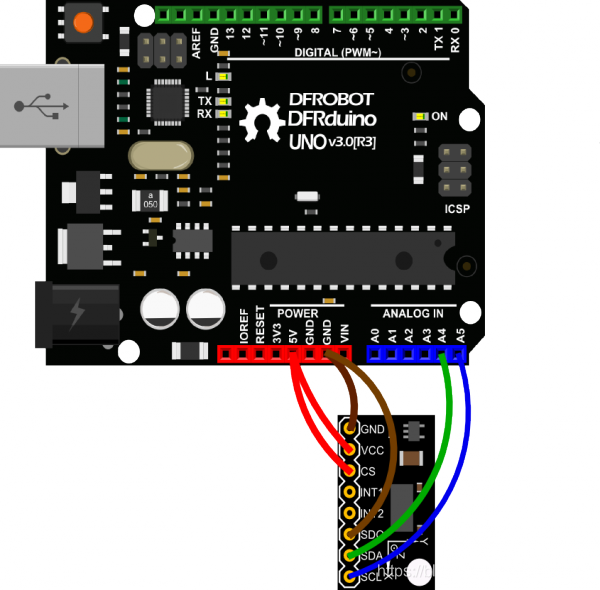
| ADXL345 | Arduino |
|---|---|
| VCC | 5V / 3V3 |
| GND | GND |
| CS | 5V / 3V3 |
| SDO | GND |
| SDA | A4 |
| SCL | A5 |
注:该连线方式适用于ADXL345的IIC通讯方式与Uno的通讯。如果您使用其他控制板,IIC管脚可能有所不同,请查阅对应管脚确保连线正确。如需使用ADXL345的SPI通讯模式,请查阅其数据手册。
样例代码
复制以下代码到您的Arduino IDE中并上传。该代码是用来收集传感器三轴加速度值,并计算Roll及Pitch角度信息。
#include <Wire.h>#define DEVICE (0x53)      //ADXL345 device address
#define TO_READ (6)        //num of bytes we are going to read each time (two bytes for each axis)byte buff[TO_READ] ;        //6 bytes buffer for saving data read from the device
char str[512];              //string buffer to transform data before sending it to the serial port
int regAddress = 0x32;      //first axis-acceleration-data register on the ADXL345
int x, y, z;				        //three axis acceleration data
double roll = 0.00, pitch = 0.00;		//Roll & Pitch are the angles which rotate by the axis X and y
//in the sequence of R(x-y-z),more info visit
// https://www.dfrobot.com/wiki/index.php?title=How_to_Use_a_Three-Axis_Accelerometer_for_Tilt_Sensing#Introductionvoid setup() {Wire.begin();         // join i2c bus (address optional for master)Serial.begin(9600);  // start serial for output//Turning on the ADXL345writeTo(DEVICE, 0x2D, 0);      writeTo(DEVICE, 0x2D, 16);writeTo(DEVICE, 0x2D, 8);
}void loop() {readFrom(DEVICE, regAddress, TO_READ, buff); //read the acceleration data from the ADXL345//each axis reading comes in 10 bit resolution, ie 2 bytes.  Least Significat Byte first!!//thus we are converting both bytes in to one intx = (((int)buff[1]) << 8) | buff[0];   y = (((int)buff[3])<< 8) | buff[2];z = (((int)buff[5]) << 8) | buff[4];//we send the x y z values as a string to the serial portSerial.print("The acceleration info of x, y, z are:");sprintf(str, "%d %d %d", x, y, z);  Serial.print(str);Serial.write(10);//Roll & Pitch calculateRP_calculate();Serial.print("Roll:"); Serial.println( roll ); Serial.print("Pitch:"); Serial.println( pitch );Serial.println("");//It appears that delay is needed in order not to clog the portdelay(50);
}//---------------- Functions
//Writes val to address register on device
void writeTo(int device, byte address, byte val) {Wire.beginTransmission(device); //start transmission to device Wire.write(address);        // send register addressWire.write(val);        // send value to writeWire.endTransmission(); //end transmission
}//reads num bytes starting from address register on device in to buff array
void readFrom(int device, byte address, int num, byte buff[]) {Wire.beginTransmission(device); //start transmission to device Wire.write(address);        //sends address to read fromWire.endTransmission(); //end transmissionWire.beginTransmission(device); //start transmission to deviceWire.requestFrom(device, num);    // request 6 bytes from deviceint i = 0;while(Wire.available())    //device may send less than requested (abnormal){ buff[i] = Wire.read(); // receive a bytei++;}Wire.endTransmission(); //end transmission
}//calculate the Roll&Pitch
void RP_calculate(){double x_Buff = float(x);double y_Buff = float(y);double z_Buff = float(z);roll = atan2(y_Buff , z_Buff) * 57.3;pitch = atan2((- x_Buff) , sqrt(y_Buff * y_Buff + z_Buff * z_Buff)) * 57.3;
}
Micropython示例
from machine import Pin,I2C
import ADXL345
import timei2c = I2C(scl=Pin(22),sda=Pin(21), freq=10000)
adx = ADXL345.ADXL345(i2c)while True:x=adx.xValuey=adx.yValuez=adx.zValueprint('The acceleration info of x, y, z are:%d,%d,%d'%(x,y,z))roll,pitch = adx.RP_calculate(x,y,z)print('roll=',roll)print('pitch=',pitch)time.sleep_ms(50)
结果
打开串口监视窗口,可以看到类似下图的数据,分别为:三轴加速度的数据,按照R-xyz旋转顺序时的Roll及Pitch角。按各轴旋转可以观测到相应的数据变化。
