图像的基本操作
在GDI+中,对图像的处理主要靠两个类,Image类和Bitmap类,Bitmap类是在Image类的基础上派生出来的。这里主要讲Image类的使用,Image类支持对BMP, GIF, JPEG, PNG, TIFF, 和 EMF,尤其注意,在PNG图像中,包含ALPHA通道,所以能实现不规则图像;
一、图像的打开与显示
图像打开
我们在前言部分已经讲到,在GDI+中,对图像的处理主要靠两个类,Image类和Bitmap类,在Image类的构造函数中,可以直接加载图片供开发者使用,其加载方式为:
Image(filename, useEmbeddedColorManagement)
Image(stream, useEmbeddedColorManagement) ;//这个不讲了,在一般不用,只在剪切保存图片时有用filename:[in]文件名,(可以是绝对地址,也可以是相对地址)
useEmbeddedColorManament:[in]是否使用在保存在图片中的色彩校正信息(如ICM、Gamma较正),该参数默认值为FALSE;
显示图片
对于图像文件的显示,GDI+主要使用DrawImage函数来完成。DrawImage函数是GDI+功能最强大、调用方式最为灵活的函数中的一种。能够实现在GDI中使用BitBlt函数不能实现的功能(如图片的任意角度旋转、倒置及插值运算),看下DrawImage的形式:
DrawImage(Image* image, Point* destPoints, INT count)
DrawImage(Image* image, PointF* destPoints, INT count)
DrawImage(Image* image, Point* destPoints, INT count, INT srcx, INT srcy, INT srcwidth, INT srcheight, Unit srcUnit, ImageAttributes* imageAttributes, DrawImageAbort callback, VOID* callbackData)
DrawImage(Image* image, PointF* destPoints, INT count, REAL srcx, REAL srcy, REAL srcwidth, REAL srcheight, Unit srcUnit, ImageAttributes* imageAttributes, DrawImageAbort callback, VOID* callbackData)
DrawImage(Image* image, Rect& destRect, INT srcx, INT srcy, INT srcwidth, INT srcheight, Unit srcUnit, ImageAttributes* imageAttributes, DrawImageAbort callback, VOID* callbackData)
DrawImage(Image* image, RectF& destRect, REAL srcx, REAL srcy, REAL srcwidth, REAL srcheight, Unit srcUnit, ImageAttributes* imageAttributes, DrawImageAbort callback, VOID* callbackData)
DrawImage(Image* image, Point& point)
DrawImage(Image* image, PointF& point)
DrawImage(Image* image, Rect& rect)
DrawImage(Image* image, RectF& rect)
DrawImage(Image* image, INT x, INT y)
DrawImage(Image* image, REAL x, REAL y)
DrawImage(Image* image, INT x, INT y, INT srcx, INT srcy, INT srcwidth, INT srcheight, Unit srcUnit)
DrawImage(Image* image, REAL x, REAL y, REAL srcx, REAL srcy, REAL srcwidth, REAL srcheight, Unit srcUnit)
DrawImage(Image* image, INT x, INT y, INT width, INT height)
DrawImage(Image* image, REAL x, REAL y, REAL width, REAL height) DrawImage(Image* image, PointF* destPoints, INT count)
DrawImage(Image* image, PointF* destPoints, INT count, REAL srcx, REAL srcy, REAL srcwidth, REAL srcheight, Unit srcUnit, ImageAttributes* imageAttributes, DrawImageAbort callback, VOID* callbackData)
DrawImage(Image* image, Rect& destRect, INT srcx, INT srcy, INT srcwidth, INT srcheight, Unit srcUnit, ImageAttributes* imageAttributes, DrawImageAbort callback, VOID* callbackData)
DrawImage(Image* image, PointF& point)
DrawImage(Image* image, RectF& rect)
DrawImage(Image* image, INT x, INT y)
DrawImage(Image* image, INT x, INT y, INT srcx, INT srcy, INT srcwidth, INT srcheight, Unit srcUnit)
DrawImage(Image* image, INT x, INT y, INT width, INT height) DrawImage(Image* image, Rect& destRect, INT srcx, INT srcy, INT srcwidth, INT srcheight, Unit srcUnit, ImageAttributes* imageAttributes, DrawImageAbort callback, VOID* callbackData) image:[in]图像文件对象;
destRect:[in]目标显示区域
srcx:[in]要截取的目标位置,在原图中的X点坐标
srcy:[in]要截取的目标位置,在原图中的Y坐标
srcwidth:[in]要截取的目标图像的宽度
srcheight:[in]要截取的目标图像的高度
注意:由于是截取一块图像作为显示图像在目标区域中显示,所以这就出现了问题
1、当截取的图像比目标区域小呢?
这时,就是将截取的图像拉伸,以至完全填充到目标区域
2、当截取的图像比目标区域大呢?
这里,就会将截取的图像缩小并平铺到目标区域中,并不会截取一部分显示
看示例:(放大、缩小)
Image image(L"wlh.bmp");
UINT width=image.GetWidth();
UINT height=image.GetHeight();
//原图显示
graphics.DrawImage(&image,RectF(0,0,width,height));
//缩小并平铺
graphics.TranslateTransform(width+10,0);
graphics.DrawImage(&image,RectF(0,0,width/2,height/2-40));
//放大并平铺,将在原图指定区域截取的图像,填充到目标区域中,填充时采用了缩放模式
graphics.TranslateTransform(width/2+10,0);
RectF destinationRect(0,0,1.4*width,1.4*height);
graphics.DrawImage(&image,destinationRect,20,20,width/2,height,UnitPixel);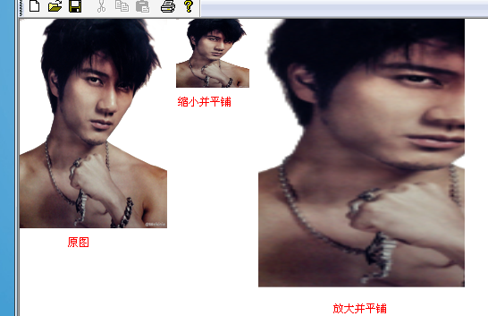
二、 使用插补模式控制图形缩放质量
首先考虑两个问题:
1、在拉伸图像时,假设图像会被拉大好几倍,如何用原来的那些像素点来填充拉大后的图像,就出现了问题,比如,原来一个像素点,在拉大图像后,这个像素点周围会变得空白,如何运用算法填充这些空白呢?
2、在缩小图像时,同样假设图像缩小为原来的1/5,那么就说明在原图像中,每5个像素,会被整合成一个像素,那这些像素怎么整合呢?哪种整合方法更好一点呢?
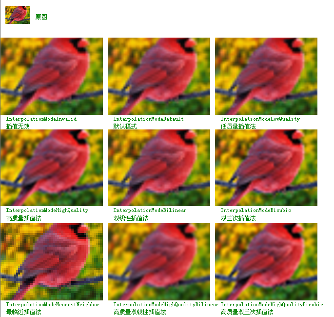
以上这两上放、大缩小时,如何填充被放大的空间,如何整合缩小的像素,这些问题,这就是插补模式要考虑的问题,插补模式又称为“插值模式”,是指如何计算两个终点之间的中间值。也就是定义了很多种算法,这些算法的效果决定了缩放后图像的质量。
GDI+中使用Graphics类的SetInterpolationMode(设置插值模式)函数来指定插补算法。看下函数定义:
Status SetInterpolationMode(InterpolationMode interpolationMode
);enum InterpolationMode{InterpolationModeInvalid = QualityModeInvalid,//插值无效InterpolationModeDefault = QualityModeDefault,//默认模式InterpolationModeLowQuality = QualityModeLow,//低质量插值法InterpolationModeHighQuality = QualityModeHigh,//高质量插值法InterpolationModeBilinear,//双线性插值法InterpolationModeBicubic,//双三次插值法InterpolationModeNearestNeighbor,//最临近插值法InterpolationModeHighQualityBilinear,//高质量双线性插值法InterpolationModeHighQualityBicubic//高质量双三次插值法
};
看一个简单的应用的例子吧:(最临近插值法)
Image image(L"bird.bmp");
UINT width=image.GetWidth();
UINT height=image.GetHeight();
Matrix matrix;
graphics.GetTransform(&matrix);
graphics.DrawImage(&image,RectF(0,0,width,height));graphics.TranslateTransform(width+10,0);
RectF destinationRect(0,0,2*width,2*height);
graphics.SetInterpolationMode(InterpolationModeNearestNeighbor);
graphics.DrawImage(&image,destinationRect,20,20,width/2,height/2,UnitPixel);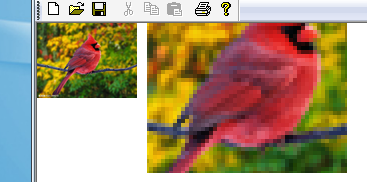
结论:由上面的所有扩大结果来看,只有“最临近插值法”会产生马赛克,而PS和其它的图像处理工具都是用的它。可能是因为它的资源消耗比较小,要注意,不同插值模式对系统资源的消耗也不同,其中高质量双三次插值方式对系统资源的消耗最大。
三、图像操作
图片的简单旋转
利用Bitmap或Image对象的RotateFilip函数就可以实现图像的旋转和翻转了。该函数的调用方法为:
Status RotateFlip(RotateFlipType rotateFlipType
);enum RotateFlipType{RotateNoneFlipNone = 0,//不旋转不翻转Rotate90FlipNone = 1,//旋转90度不翻转Rotate180FlipNone = 2,//旋转180度不翻转Rotate270FlipNone = 3,//旋转270度不翻转RotateNoneFlipX = 4,//不旋转水平翻转Rotate90FlipX = 5,//旋转90度水平翻转Rotate180FlipX = 6,//旋转180度水平翻转Rotate270FlipX = 7,//旋转270度水平翻转RotateNoneFlipY = Rotate180FlipX,//往下的这些跟上面的效果都是一样的,所以一般都不用下面的几个Rotate90FlipY = Rotate270FlipX,Rotate180FlipY = RotateNoneFlipX,Rotate270FlipY = Rotate90FlipX,RotateNoneFlipXY = Rotate180FlipNone,Rotate90FlipXY = Rotate270FlipNone,Rotate180FlipXY = RotateNoneFlipNone,Rotate270FlipXY = Rotate90FlipNone
};
看个简单示例吧(RotateNoneFlipX--不旋转水平翻转)
Image image(L"bird.bmp");
UINT width=image.GetWidth();
UINT height=image.GetHeight();
Matrix matrix;
graphics.GetTransform(&matrix);
graphics.DrawImage(&image,RectF(0,0,width/2,height/2));graphics.SetTransform(&matrix);
graphics.TranslateTransform(width/2+10,0);
Image *img2=image.Clone();
img2->RotateFlip(RotateNoneFlipX);
graphics.DrawImage(img2,RectF(0,0,width/2,height/2));
使用缩略图
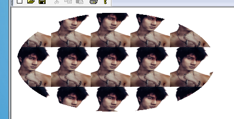
GDI+中可以定制缩略图,具体办法是使用Image类的GetThumbnailImage来实现,该函数的调用方法为:
Image* GetThumbnailImage(UINT thumbWidth,UINT thumbHeight,GetThumbnailImageAbort callback,VOID* callbackData
);thumbWidh、thumbHeightt:[in]指明需要建立的缩略图宽度和高度,在IMG中不会自动保持宽高比,会根据指定的高度和宽度完全填充;
callback、callbackData:[in]建立缩略图时要用到的回调函数及回调函数中数据的存放地址;在GDI+1.0版中不能使用此功能;注意XP中使用也是1.0版
注意:这里虽是指获取缩略图,但当所指区域比原图大时,就会把原图放大,与DrawImage指定目标区域,没什么区别;
示例:
graphics.SetInterpolationMode(InterpolationModeHighQualityBicubic);
Image img(L"wlh.bmp");
float shear=img.GetHeight()/img.GetWidth();//获取高/宽比,以至缩放时不变形
Image *pThumbnail=img.GetThumbnailImage(80,80*shear,NULL,NULL);//高度乘以高宽比TextureBrush picBrush(pThumbnail);
graphics.FillEllipse(&picBrush,RectF(10,10,400,200));
克隆图片
克隆复制是GDI+中的新概念,对图片克隆的范围可以是整体,也可以是局部的。实现克隆的办法是使用Bitmap类/Image类的Clone成员函数;需要注意的是,Bitmap类可以实现局部克隆和整体克隆,而Image类只能整体克隆;
我们看下Bitmap类的Clone函数:
Clone()
Clone(Rect& rect, PixelFormat format)
Clone(RectF& rect, PixelFormat format)
Clone(INT x, INT y, INT width, INT height, PixelFormat format)
Clone(REAL x, REAL y, REAL width, REAL, height, PixelFormat format) rect:[in]要克隆的区域,指在原图中的坐标区域矩形;
x,y:[in]要克隆区域的X,Y坐标;
width,height:[in]要克隆区域的宽度和高度;
看下示例(将图片通过克隆,分成四块):
Bitmap bmp(L"wlh.bmp");
INT height=bmp.GetHeight();
INT width=bmp.GetWidth();RectF dest[4];
dest[0]=RectF(0,0,width/2,height/2);
dest[1]=RectF(width/2,0,width/2,height/2);
dest[2]=RectF(0,height/2,width/2,height/2);
dest[3]=RectF(width/2,height/2,width/2,height/2);
//把原图像分为分四块克隆
Bitmap *s[4];
s[0]=bmp.Clone(dest[0],PixelFormatDontCare);
s[1]=bmp.Clone(dest[1],PixelFormatDontCare);
s[2]=bmp.Clone(dest[2],PixelFormatDontCare);
s[3]=bmp.Clone(dest[3],PixelFormatDontCare);
//绘图
graphics.DrawImage(s[0],RectF(0,0,width/2,height/2));
graphics.DrawImage(s[1],RectF(width/2+10,0,width/2,height/2));
graphics.DrawImage(s[2],RectF(0,height/2+10,width/2,height/2));
graphics.DrawImage(s[3],RectF(width/2+10,height/2+10,width/2,height/2));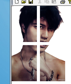
投射与倾斜
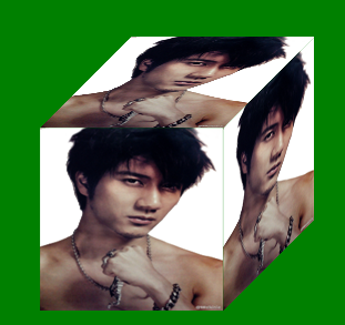
在前面我们讲了,在DrawImge可以指定目标区域矩形,然后图像就会自适应这个矩形,所以按说我们可以用指定目标矩形的方式来实现下图的效果;
但是,我们得一个个计算这些矩形的四个点坐标,很难,还好,DrawImage为我们提供了一个重载函数,函数如下:
Status DrawImage(Image* image,const Point* destPoints,INT count
);image:[in]图像对象
destPoints:[in]目标区域的点的组合,这里只包含三个点,左上,右上,左下,对于第四个点的坐标,GDI+会根据平行四边形原理自动计算位置;
count:[in]destPoints数组里的点的个数,必须等于3
示例:(实现上面的三面立方体)
//清空原背景色,然后将背景色换为绿色
graphics.Clear(Color::Green);
//设置填充模式
graphics.SetInterpolationMode(InterpolationModeHighQualityBicubic);
Image img(L"wlh.bmp");
INT left=100;
INT top=200;
INT width=img.GetWidth();
INT height=img.GetHeight();
//正面
PointF desFace[]={PointF(left,top),PointF(left+width,top),PointF(left,top+width),
};
graphics.DrawImage(&img,desFace,3);
//上面投射
PointF destTop[]={PointF(left+width/2,top-width/2),PointF(left+width/2+width,top-width/2),PointF(left,top),
};
graphics.DrawImage(&img,destTop,3);
//侧面投射
PointF desRight[]={PointF(left+width,top),PointF(left+width/2+width,top-width/2),PointF(left+width,top+width)
};
graphics.DrawImage(&img,desRight,3);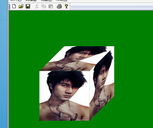
调整图像的色彩信息
色彩调整,主要靠ImageAttributes类中的函数来操作的,所以这里也就是对ImageAttributes类中各函数功能的讲解;这里说色彩较正,其实就是通过色彩变换矩阵,对色彩所进行的操作。
一、启用与禁用色彩校正
使用色彩变换矩阵,程序开发人员可以使用ImageAttributes对象修改在绘图平面上的图片输出行为:使用修改后的色彩对应关系。在修改过程中,可以临时禁用或启用色彩校正行为。ImageAttributes类的成员函数SetNoOp和ClearNoOp实现了对色彩校正的临时关闭与启用,其函数调用格式为:
Status SetNoOp(ColorAdjustType type);
Status ClearNoOp(ColorAdjustType type);
其中,ColorAdjustType是个枚举类,指明了几种色彩调整对象;
enum ColorAdjustType{ColorAdjustTypeDefault,//匹配全部对象ColorAdjustTypeBitmap,//仅匹配图像,虽然这里用的是Bitmap,但不仅限于BMP图像,只要是图像都用这个ColorAdjustTypeBrush,//仅匹配画刷ColorAdjustTypePen,//仅匹配画笔ColorAdjustTypeText,//仅匹配对文字的调整ColorAdjustTypeCount,//不用ColorAdjustTypeAny//不用,最后两个是不用的;
};Image img(L"wlh.bmp");
int width=img.GetWidth();
int height=img.GetHeight();
//原图
graphics.DrawImage(&img,RectF(0,0,width,height));
//应用色彩变换
graphics.TranslateTransform(width+10,0);
ColorMatrix colorMatrix={0.0f,1.0f,0.0f,0.0f,0.0f,0.0f,1.0f,0.0f,0.0f,0.0f,0.0f,0.0f,1.0f,0.0f,0.0f,0.0f,0.0f,0.0f,1.0f,0.0f,0.0f,0.0f,0.0f,0.0f,1.0f
};
ImageAttributes imgattr;
imgattr.SetColorMatrix(&colorMatrix,ColorMatrixFlagsDefault,ColorAdjustTypeBitmap);
graphics.DrawImage(&img,RectF(0,0,img.GetWidth(),img.GetHeight()),0,0,img.GetWidth(),img.GetHeight(),UnitPixel,&imgattr);
//清除对图像的变换
imgattr.SetNoOp(ColorAdjustTypeBitmap);
graphics.TranslateTransform(width+10,0);
graphics.DrawImage(&img,RectF(0,0,img.GetWidth(),img.GetHeight()),0,0,img.GetWidth(),img.GetHeight(),UnitPixel,&imgattr);
//清除刚才的清除操作
imgattr.ClearNoOp(ColorAdjustTypeBitmap);
graphics.TranslateTransform(width+10,0);
graphics.DrawImage(&img,RectF(0,0,img.GetWidth(),img.GetHeight()),0,0,img.GetWidth(),img.GetHeight(),UnitPixel,&imgattr);
二、设置透明色范围(ImageAttributes::SetColorKey)
在上面的应用中,我们可以通过对图像的图像逐个像素操作将指定的颜色设定为透明色,也可以通过ColorMap将指定的几个颜色替换为其它颜色,在这里,是另一种设定图片透明的方法——设定关键色(ColorKey),关键色就是指要设为透明的颜色值。通过ImageAttributes类的SetColorKey方法,定义如下:
Status SetColorKey(const Color& colorLow,const Color& colorHigh,ColorAdjustType type
);colorLow:[in]透明色的最低值;
colorHigh:[in]透明色的最高值;
type:[in]指定要设定关键色的对象;
注意:假设colorLow设定为Color(100, 95, 30),colorHigh设定为:Color(250, 245, 60);那么对于颜色值Color(x,y,z);如果100<x<250 and 95<y<245 and 30<z<60,那么它就会被设为透明色;
示例:(去除王力宏图片的背景,背景色我用PS加了个渐变,从Color(200,200,200)到Color(255,255,255),所以这个范围也是要设定为关键色的范围)
代码:
Image img(L"wlh2.bmp");
graphics.Clear(Color(255,0,255,0));
//绘制原图
graphics.DrawImage(&img,RectF(0,0,img.GetWidth(),img.GetHeight()));
//设置透明色范围
graphics.TranslateTransform(img.GetWidth()+10,0);
ImageAttributes imgAttributes;
imgAttributes.SetColorKey(Color(255,200,200,200),Color(255,255,255,255),ColorAdjustTypeBitmap);
graphics.DrawImage(&img,RectF(0,0,img.GetWidth(),img.GetHeight()),0,0,img.GetWidth(),img.GetHeight(),UnitPixel,&imgAttributes);
注意:在图片上也可以看得到,王的鼻尖处也变成了透明色,这是因为它的色彩值范围在设定的ColorKey的范围内。
