我们将开始编写与顶点缓冲区文章中的示例类似的代码,但这次将绘制单个 F 而不是一堆圆,并使用索引缓冲区来保持数据更小。
让我们在像素空间而不是裁剪空间中工作,就像 Canvas 2D API 我们将制作一个 F,将从 6 个三角形构建它
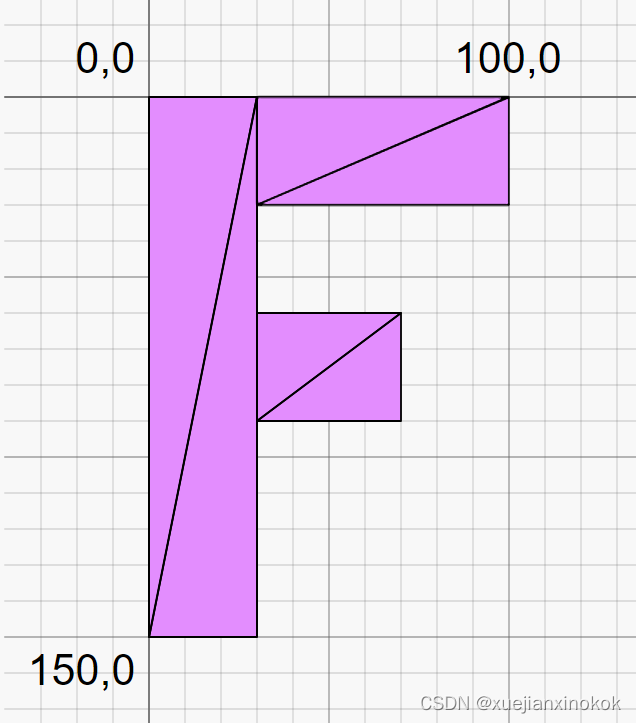
这是 F 的数据
function createFVertices() {const vertexData = new Float32Array([// left column0 ,   0, //030,   0, //10 , 150, //230, 150, //3// top rung30 ,  0, //4100,  0, //530 , 30, //6100, 30, //7// middle rung30, 60,  //870, 60,  //930, 90,  //1070, 90,  //11]);const indexData = new Uint32Array([0,  1,  2,    2,  1,  3,  // left column4,  5,  6,    6,  5,  7,  // top run8,  9, 10,   10,  9, 11,  // middle run]);return {vertexData,indexData,numVertices: indexData.length,};
}
上面的顶点数据在像素空间中,因此需要将其转换为裁剪空间。可以通过将分辨率传递给着色器并进行一些数学运算来做到这一点。下边是操作步骤。
struct Uniforms {color: vec4f,resolution: vec2f,
};struct Vertex {@location(0) position: vec2f,
};struct VSOutput {@builtin(position) position: vec4f,
};@group(0) @binding(0) var<uniform> uni: Uniforms;@vertex fn vs(vert: Vertex) -> VSOutput {var vsOut: VSOutput;let position = vert.position;// convert the position from pixels to a 0.0 to 1.0 valuelet zeroToOne = position / uni.resolution;// convert from 0 <-> 1 to 0 <-> 2let zeroToTwo = zeroToOne * 2.0;// covert from 0 <-> 2 to -1 <-> +1 (clip space)let flippedClipSpace = zeroToTwo - 1.0;// flip Ylet clipSpace = flippedClipSpace * vec2f(1, -1);vsOut.position = vec4f(clipSpace, 0.0, 1.0);return vsOut;
}@fragment fn fs(vsOut: VSOutput) -> @location(0) vec4f {return uni.color;
}
使用顶点位置并将其除以分辨率。这给了一个在画布上从 0 到 1 的值。然后乘以 2 以获得画布上从 0 到 2 的值。然后减去 1。现在我们的值在裁剪空间中,但它被翻转了,因为裁剪空间向上 Y 正向,而画布 2d 向下 Y 正向。所以将 Y 乘以 -1 来翻转它。现在有了所需的裁剪空间值,可以从着色器中输出它。
现在只有一个属性,所以渲染管线看起来像这样
const pipeline = device.createRenderPipeline({label: 'just 2d position',layout: 'auto',vertex: {module,entryPoint: 'vs',buffers: [{arrayStride: (2) * 4, // (2) floats, 4 bytes eachattributes: [{shaderLocation: 0, offset: 0, format: 'float32x2'}, // position],},],},fragment: {module,entryPoint: 'fs',targets: [{ format: presentationFormat }],},});
需要为uniforms设置一个缓冲区
// color, resolution, paddingconst uniformBufferSize = (4 + 2) * 4 + 8;const uniformBuffer = device.createBuffer({label: 'uniforms',size: uniformBufferSize,usage: GPUBufferUsage.UNIFORM | GPUBufferUsage.COPY_DST,});const uniformValues = new Float32Array(uniformBufferSize / 4);// offsets to the various uniform values in float32 indicesconst kColorOffset = 0;const kResolutionOffset = 4;const colorValue = uniformValues.subarray(kColorOffset, kColorOffset + 4);const resolutionValue = uniformValues.subarray(kResolutionOffset, kResolutionOffset + 2);// The color will not change so let's set it once at init timecolorValue.set([Math.random(), Math.random(), Math.random(), 1]);
在渲染时需要设置分辨率
function render() {...// Set the uniform values in our JavaScript side Float32ArrayresolutionValue.set([canvas.width, canvas.height]);// upload the uniform values to the uniform bufferdevice.queue.writeBuffer(uniformBuffer, 0, uniformValues);
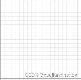
Before we run it lets make the background of the canvas look like graph paper. We’ll set it’s scale so each grid cell of the graph paper is 10x10 pixels and every 100x100 pixels we’ll draw a bolder line.
在运行它之前,需要让画布的背景看起来像方格纸。将设置它的比例,使方格纸的每个网格单元为 10x10 像素,且每 100x100 像素我们将绘制一条粗线。效果图如下
:root {--bg-color: #fff;--line-color-1: #AAA;--line-color-2: #DDD;
}
@media (prefers-color-scheme: dark) {:root {--bg-color: #000;--line-color-1: #666;--line-color-2: #333;}
}
canvas {display: block;  /* make the canvas act like a block   */width: 100%;     /* make the canvas fill its container */height: 100%;background-color: var(--bg-color);background-image: linear-gradient(var(--line-color-1) 1.5px, transparent 1.5px),linear-gradient(90deg, var(--line-color-1) 1.5px, transparent 1.5px),linear-gradient(var(--line-color-2) 1px, transparent 1px),linear-gradient(90deg, var(--line-color-2) 1px, transparent 1px);background-position: -1.5px -1.5px, -1.5px -1.5px, -1px -1px, -1px -1px;background-size: 100px 100px, 100px 100px, 10px 10px, 10px 10px;
}
上面的 CSS 应该处理浅色和深色情况。
到目前为止,所有的示例都使用了不透明的画布。为了使其透明,以便可以看到刚刚设置的背景,需要进行一些更改。
首先需要在配置画布为 ‘premultiplied’ 时设置 alphaMode 。它默认为 ‘opaque’ 。
context.configure({device,format: presentationFormat,alphaMode: 'premultiplied',});
然后需要在 GPURenderPassDescriptor 中将画布清除为 0, 0, 0, 0。因为默认的 clearValue 是 0, 0, 0, 0 可以删除将它设置为其他内容。
const renderPassDescriptor = {label: 'our basic canvas renderPass',colorAttachments: [{// view: <- to be filled out when we render//clearValue: [0.3, 0.3, 0.3, 1],loadOp: 'clear',storeOp: 'store',},],};
有了这个,这是F的显示结果
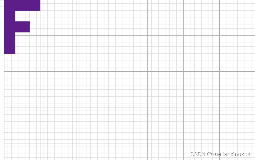
注意 F 相对于它后面的网格的大小。 F 数据的顶点位置使 F 宽 100 像素,高 150 像素,与我们显示的相匹配。 F 从 0,0 开始,向右延伸到 100,0,向下延伸到 0,150
现在已经有了基础,让我们添加平移变换。
Translation is just the process of moving things so all we need to do is add translation to our uniforms and add that to our position
平移变换只是移动事物的过程,所以需要做的就是将平移添加到我们的uniforms 并将其与位置相加
struct Uniforms {color: vec4f,resolution: vec2f,translation: vec2f, //here
};struct Vertex {@location(0) position: vec2f,
};struct VSOutput {@builtin(position) position: vec4f,
};@group(0) @binding(0) var<uniform> uni: Uniforms;@vertex fn vs(vert: Vertex) -> VSOutput {var vsOut: VSOutput;// Add in the translation//let position = vert.position;let position = vert.position + uni.translation;// convert the position from pixels to a 0.0 to 1.0 valuelet zeroToOne = position / uni.resolution;// convert from 0 <-> 1 to 0 <-> 2let zeroToTwo = zeroToOne * 2.0;// covert from 0 <-> 2 to -1 <-> +1 (clip space)let flippedClipSpace = zeroToTwo - 1.0;// flip Ylet clipSpace = flippedClipSpace * vec2f(1, -1);vsOut.position = vec4f(clipSpace, 0.0, 1.0);return vsOut;
}@fragment fn fs(vsOut: VSOutput) -> @location(0) vec4f {return uni.color;
}
需要为uniforms 缓冲区增加空间
// color, resolution, padding//const uniformBufferSize = (4 + 2) * 4 + 8;// color, resolution, translationconst uniformBufferSize = (4 + 2 + 2) * 4; //hereconst uniformBuffer = device.createBuffer({label: 'uniforms',size: uniformBufferSize,usage: GPUBufferUsage.UNIFORM | GPUBufferUsage.COPY_DST,});const uniformValues = new Float32Array(uniformBufferSize / 4);// offsets to the various uniform values in float32 indicesconst kColorOffset = 0;const kResolutionOffset = 4;const kTranslationOffset = 6; //hereconst colorValue = uniformValues.subarray(kColorOffset, kColorOffset + 4);const resolutionValue = uniformValues.subarray(kResolutionOffset, kResolutionOffset + 2);const translationValue = uniformValues.subarray(kTranslationOffset, kTranslationOffset + 2); //here
然后需要在渲染时设置平移
const settings = {translation: [0, 0],};function render() {...// Set the uniform values in our JavaScript side Float32ArrayresolutionValue.set([canvas.width, canvas.height]);translationValue.set(settings.translation);//here// upload the uniform values to the uniform bufferdevice.queue.writeBuffer(uniformBuffer, 0, uniformValues);
最后添加一个 UI,这样就可以调整平移距离
import GUI from '/3rdparty/muigui-0.x.module.js';...const settings = {translation: [0, 0],};const gui = new GUI();gui.onChange(render);gui.add(settings.translation, '0', 0, 1000).name('translation.x');gui.add(settings.translation, '1', 0, 1000).name('translation.y');
现在添加了平移
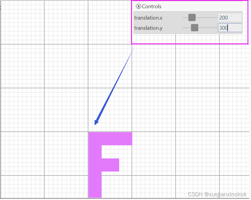
请注意它与我们的像素网格相匹配。如果我们将平移设置为 200,300,则绘制 F 时其 0,0 左上角顶点位于 200,300。
这篇文章可能看起来非常简单。尽管我们将其命名为“offset”,但之前已经在几个示例中使用了平移。本文是系列文章的一部分。虽然它很简单,但希望它的要点在我们继续本系列的上下文中有意义。
接下来是旋转。
原文地址

