【基于 Arduino 的 RFID门锁】
- 1. 概述
- 2. 射频识别的工作原理
- 3. RFID 和 Arduino
- 4. Arduino RFID门锁门禁项目
- 5. 源代码
在本教程中,我们将了解什么是 RFID,它是如何工作的以及如何制作基于 Arduino 的 RFID 门锁。您可以观看以下视频或阅读下面的书面教程以获取更多详细信息。
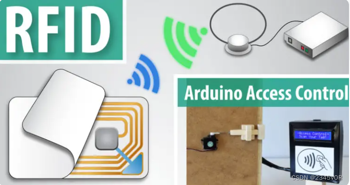
1. 概述
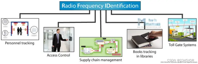
RFID代表射频识别,它是一种非接触式技术,广泛用于许多行业,用于人员跟踪,访问控制,供应链管理,图书馆书籍跟踪,收费站系统等任务。
2. 射频识别的工作原理
RFID系统由两个主要组件组成,一个应答器或位于我们要识别的物体上的标签,以及一个收发器或阅读器。

RFID阅读器由射频模块,控制单元和产生高频电磁场的天线线圈组成。另一方面,标签通常是一个无源元件,仅由天线和电子微芯片组成,因此当它接近收发器的电磁场时,由于感应,其天线线圈中会产生电压,该电压用作微芯片的电源。
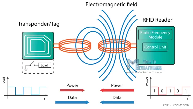
现在,当标签通电时,它可以从阅读器中提取传输的消息,并且为了将消息发送回阅读器,它使用一种称为加载操作的技术。打开和关闭标签天线上的负载将影响读取器天线的功耗,这可以测量为电压降。电压的这种变化将被捕获为一和零,这就是数据从标签传输到读取器的方式。
在读取器和标签之间还有另一种数据传输方式,称为反向散射耦合。在这种情况下,标签使用部分接收功率来产生另一个电磁场,该电磁场将被阅读器的天线拾取。
3. RFID 和 Arduino
所以这是基本的工作原理,现在让我们看看如何将RFID与Arduino一起使用并构建我们自己的RFID门锁。我们将使用基于MIFARE协议和MFRC522 RFID阅读器的标签,其成本仅为几美元。
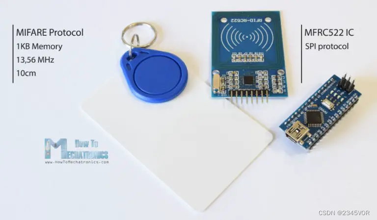
这些标签具有1kb的内存,并具有可以进行算术运算的微芯片。它们的工作频率为 13.56 MHz,工作距离可达 10 厘米,具体取决于天线的几何形状。如果我们将这些标签之一放在光源前面,我们可以注意到我们之前谈到的天线和微芯片。

至于RFID阅读器模块,它使用SPI协议与Arduino板进行通信,这是我们需要如何连接它们。请注意,我们必须将模块的VCC连接到3.3V,至于其他引脚,我们不必担心,因为它们具有5V容限。

连接模块后,我们需要从 GitHub 下载 MFRC522 库。该库附带了几个很好的示例,我们可以从中学习如何使用该模块。
首先,我们可以上传“DumpInfo”示例并测试我们的系统是否正常工作。现在,如果我们运行串行监视器并将标签靠近模块,阅读器将开始读取标签,标签中的所有信息将显示在串行监视器上。
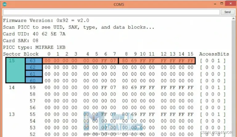
在这里,我们可以注意到标签的UID编号以及实际上分为1个扇区的16 KB内存,每个扇区分为4个块,每个块可以存储2个字节的数据。在本教程中,我们不会使用标签的任何内存,我们只使用标签的 UID 编号。
4. Arduino RFID门锁门禁项目
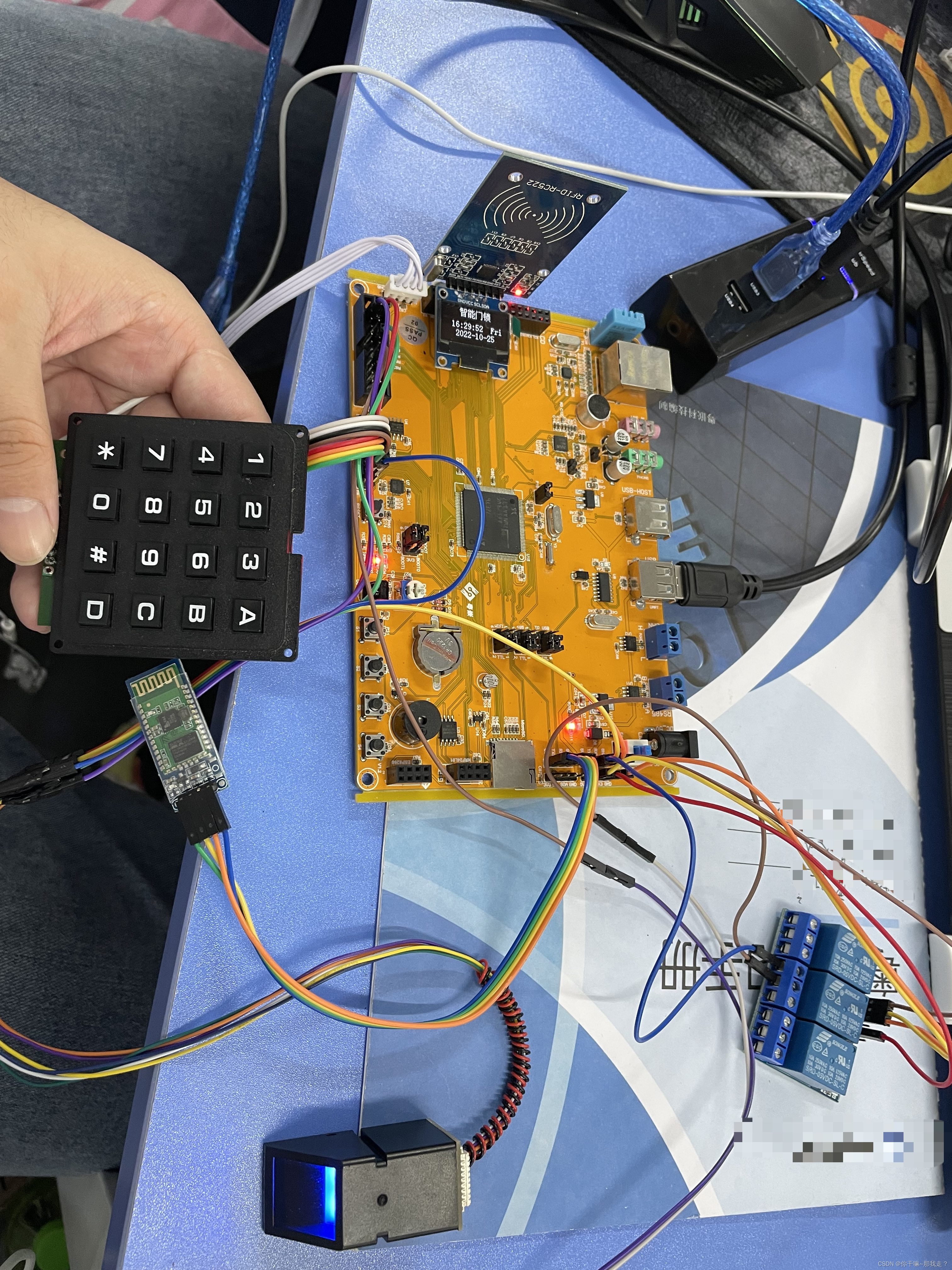
在我们浏览RFID门锁项目的代码之前,让我们看一下该项目的组件和电路原理图。
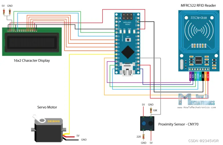
除了RFID模块外,我们还将使用接近传感器来检查门是关闭还是打开,用于锁定机构的伺服电机和字符显示。
您可以从以下链接获取此Arduino教程所需的组件:
- MFRC522 无线射频识别模块
- 伺服电机
- 液晶显示器
- Arduino Board
- 面包板和跳线
- 接近传感器
该项目具有以下工作流程:首先我们必须设置一个主标签,然后系统进入正常模式。如果我们扫描未知标签,访问将被拒绝,但如果扫描主站,我们将进入程序模式,从中我们可以添加和授权未知标签。所以现在如果我们再次扫描标签,将授予访问权限,以便我们可以打开门。
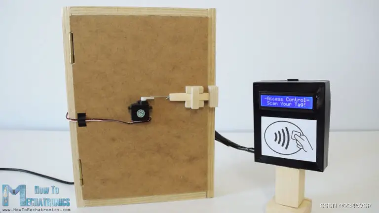
我们关门后,门会自动锁定。如果我们想从系统中删除标签,我们只需要再次进入程序模式,扫描 know 标签,它就会被删除。
5. 源代码
现在让我们看一下代码。 因此,首先我们需要包括RFID模块,显示器和伺服电机的库,定义以下程序所需的一些变量以及创建库的实例。
#include <SPI.h>
#include <MFRC522.h>
#include <LiquidCrystal.h>
#include <Servo.h>#define RST_PIN   9
#define SS_PIN    10byte readCard[4];
char* myTags[100] = {};
int tagsCount = 0;
String tagID = "";
boolean successRead = false;
boolean correctTag = false;
int proximitySensor;
boolean doorOpened = false;// Create instances
MFRC522 mfrc522(SS_PIN, RST_PIN);
LiquidCrystal lcd(2, 3, 4, 5, 6, 7); //Parameters: (rs, enable, d4, d5, d6, d7)
Servo myServo; // Servo motor
Code language: Arduino (arduino)
在设置部分,首先我们初始化模块,并将伺服电机的初始值设置为锁定位置。然后我们将初始消息打印到显示屏上,并使用以下“while”循环等待,直到扫描主标签。getID() 自定义函数获取标签 UID,我们将其放入 myTags[0] 数组的第一个位置。
void setup() {// InitiatingSPI.begin();        // SPI busmfrc522.PCD_Init(); //  MFRC522lcd.begin(16, 2);   // LCD screenmyServo.attach(8);  // Servo motormyServo.write(10); // Initial lock position of the servo motor// Prints the initial messagelcd.print("-No Master Tag!-");lcd.setCursor(0, 1);lcd.print("    SCAN NOW");// Waits until a master card is scannedwhile (!successRead) {successRead = getID();if ( successRead == true) {myTags[tagsCount] = strdup(tagID.c_str()); // Sets the master tag into position 0 in the arraylcd.clear();lcd.setCursor(0, 0);lcd.print("Master Tag Set!");tagsCount++;}}successRead = false;printNormalModeMessage();
}
Code language: Arduino (arduino)
让我们来看看 getID() 自定义函数。首先,它检查阅读器附近是否放置了新标签,如果是,我们将继续进入“for”循环,该循环将获取标签的UID。我们使用的标签有 4 字节的 UID 编号,这就是为什么我们需要用这个循环进行 4 次迭代,并使用 concat() 函数将 4 个字节添加到单个 String 变量中。我们还将字符串的所有字符设置为大写,最后我们停止读取。
uint8_t getID() {// Getting ready for Reading PICCsif ( ! mfrc522.PICC_IsNewCardPresent()) { //If a new PICC placed to RFID reader continuereturn 0;}if ( ! mfrc522.PICC_ReadCardSerial()) {   //Since a PICC placed get Serial and continuereturn 0;}tagID = "";for ( uint8_t i = 0; i < 4; i++) {  // The MIFARE PICCs that we use have 4 byte UIDreadCard[i] = mfrc522.uid.uidByte[i];tagID.concat(String(mfrc522.uid.uidByte[i], HEX)); // Adds the 4 bytes in a single String variable}tagID.toUpperCase();mfrc522.PICC_HaltA(); // Stop readingreturn 1;
}
Code language: Arduino (arduino)
在我们进入主循环之前,在设置部分结束时,我们还调用 printNormalModeMessage() 自定义函数,该函数在显示屏上打印“访问控制”消息。
void printNormalModeMessage() {delay(1500);lcd.clear();lcd.print("-Access Control-");lcd.setCursor(0, 1);lcd.print(" Scan Your Tag!");
}
Code language: Arduino (arduino)
在主循环中,我们从读取接近传感器的值开始,它告诉我们门是否关闭。
int proximitySensor = analogRead(A0);
Code language: Arduino (arduino)
因此,如果门关闭,使用我们在 getID() 自定义函数中描述的相同行,我们将扫描并获取新标签的 UID。我们可以在这里注意到,由于“if”语句中的“return”行,在我们扫描标签之前,代码不会继续。
扫描标签后,我们会检查该标签是否是我们之前注册的主标签,如果这是真的,我们将进入程序模式。在这种模式下,如果我们扫描已经授权的标签,它将从系统中删除,或者如果标签未知,它将作为授权添加到系统中。
// Checks whether the scanned tag is the master tagif (tagID == myTags[0]) {lcd.clear();lcd.print("Program mode:");lcd.setCursor(0, 1);lcd.print("Add/Remove Tag");while (!successRead) {successRead = getID();if ( successRead == true) {for (int i = 0; i < 100; i++) {if (tagID == myTags[i]) {myTags[i] = "";lcd.clear();lcd.setCursor(0, 0);lcd.print(" Tag Removed!");printNormalModeMessage();return;}}myTags[tagsCount] = strdup(tagID.c_str());lcd.clear();lcd.setCursor(0, 0);lcd.print(" Tag Added!");printNormalModeMessage();tagsCount++;return;}}}
Code language: Arduino (arduino)
在程序模式之外,通过下一个“for”循环,我们检查扫描的标签是否等于任何注册的标签,我们要么解锁门,要么拒绝访问。在“else”语句的最后,我们等到门关闭,然后我们锁定门并再次打印正常模式消息。
// Checks whether the scanned tag is authorizedfor (int i = 0; i < 100; i++) {if (tagID == myTags[i]) {lcd.clear();lcd.setCursor(0, 0);lcd.print(" Access Granted!");myServo.write(170); // Unlocks the doorprintNormalModeMessage();correctTag = true;}}if (correctTag == false) {lcd.clear();lcd.setCursor(0, 0);lcd.print(" Access Denied!");printNormalModeMessage();}}// If door is open...else {lcd.clear();lcd.setCursor(0, 0);lcd.print(" Door Opened!");while (!doorOpened) {proximitySensor = analogRead(A0);if (proximitySensor > 200) {doorOpened = true;}}doorOpened = false;delay(500);myServo.write(10); // Locks the doorprintNormalModeMessage();}
Code language: Arduino (arduino)
所以这几乎是所有内容,这是项目的完整代码:
/*
* Arduino Door Lock Access Control Project
*
* by Dejan Nedelkovski, www.HowToMechatronics.com
*
* Library: MFRC522, https://github.com/miguelbalboa/rfid
*/#include <SPI.h>
#include <MFRC522.h>
#include <LiquidCrystal.h>
#include <Servo.h>#define RST_PIN   9
#define SS_PIN    10byte readCard[4];
char* myTags[100] = {};
int tagsCount = 0;
String tagID = "";
boolean successRead = false;
boolean correctTag = false;
int proximitySensor;
boolean doorOpened = false;// Create instances
MFRC522 mfrc522(SS_PIN, RST_PIN);
LiquidCrystal lcd(2, 3, 4, 5, 6, 7); //Parameters: (rs, enable, d4, d5, d6, d7)
Servo myServo; // Servo motorvoid setup() {// InitiatingSPI.begin();        // SPI busmfrc522.PCD_Init(); //  MFRC522lcd.begin(16, 2);   // LCD screenmyServo.attach(8);  // Servo motormyServo.write(10); // Initial lock position of the servo motor// Prints the initial messagelcd.print("-No Master Tag!-");lcd.setCursor(0, 1);lcd.print("    SCAN NOW");// Waits until a master card is scannedwhile (!successRead) {successRead = getID();if ( successRead == true) {myTags[tagsCount] = strdup(tagID.c_str()); // Sets the master tag into position 0 in the arraylcd.clear();lcd.setCursor(0, 0);lcd.print("Master Tag Set!");tagsCount++;}}successRead = false;printNormalModeMessage();
}void loop() {int proximitySensor = analogRead(A0);// If door is closed...if (proximitySensor > 200) {if ( ! mfrc522.PICC_IsNewCardPresent()) { //If a new PICC placed to RFID reader continuereturn;}if ( ! mfrc522.PICC_ReadCardSerial()) {   //Since a PICC placed get Serial and continuereturn;}tagID = "";// The MIFARE PICCs that we use have 4 byte UIDfor ( uint8_t i = 0; i < 4; i++) {  //readCard[i] = mfrc522.uid.uidByte[i];tagID.concat(String(mfrc522.uid.uidByte[i], HEX)); // Adds the 4 bytes in a single String variable}tagID.toUpperCase();mfrc522.PICC_HaltA(); // Stop readingcorrectTag = false;// Checks whether the scanned tag is the master tagif (tagID == myTags[0]) {lcd.clear();lcd.print("Program mode:");lcd.setCursor(0, 1);lcd.print("Add/Remove Tag");while (!successRead) {successRead = getID();if ( successRead == true) {for (int i = 0; i < 100; i++) {if (tagID == myTags[i]) {myTags[i] = "";lcd.clear();lcd.setCursor(0, 0);lcd.print("  Tag Removed!");printNormalModeMessage();return;}}myTags[tagsCount] = strdup(tagID.c_str());lcd.clear();lcd.setCursor(0, 0);lcd.print("   Tag Added!");printNormalModeMessage();tagsCount++;return;}}}successRead = false;// Checks whether the scanned tag is authorizedfor (int i = 0; i < 100; i++) {if (tagID == myTags[i]) {lcd.clear();lcd.setCursor(0, 0);lcd.print(" Access Granted!");myServo.write(170); // Unlocks the doorprintNormalModeMessage();correctTag = true;}}if (correctTag == false) {lcd.clear();lcd.setCursor(0, 0);lcd.print(" Access Denied!");printNormalModeMessage();}}// If door is open...else {lcd.clear();lcd.setCursor(0, 0);lcd.print(" Door Opened!");while (!doorOpened) {proximitySensor = analogRead(A0);if (proximitySensor > 200) {doorOpened = true;}}doorOpened = false;delay(500);myServo.write(10); // Locks the doorprintNormalModeMessage();}
}uint8_t getID() {// Getting ready for Reading PICCsif ( ! mfrc522.PICC_IsNewCardPresent()) { //If a new PICC placed to RFID reader continuereturn 0;}if ( ! mfrc522.PICC_ReadCardSerial()) {   //Since a PICC placed get Serial and continuereturn 0;}tagID = "";for ( uint8_t i = 0; i < 4; i++) {  // The MIFARE PICCs that we use have 4 byte UIDreadCard[i] = mfrc522.uid.uidByte[i];tagID.concat(String(mfrc522.uid.uidByte[i], HEX)); // Adds the 4 bytes in a single String variable}tagID.toUpperCase();mfrc522.PICC_HaltA(); // Stop readingreturn 1;
}void printNormalModeMessage() {delay(1500);lcd.clear();lcd.print("-Access Control-");lcd.setCursor(0, 1);lcd.print(" Scan Your Tag!");
}
Code language: Arduino (arduino)
我希望您喜欢本教程,并随时在下面的评论部分提出任何问题。
翻译地址:https://howtomechatronics.com/tutorials/arduino/rfid-works-make-arduino-based-rfid-door-lock/
视频地址:https://youtu.be/QSx778Gr6Y4