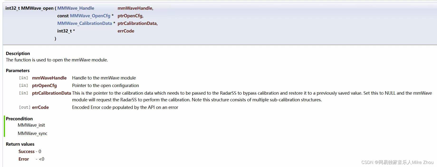
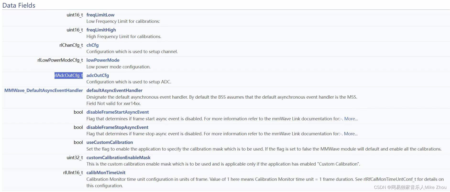
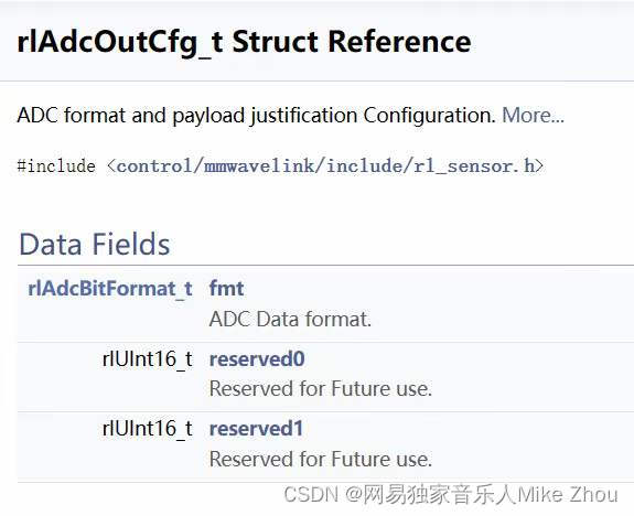
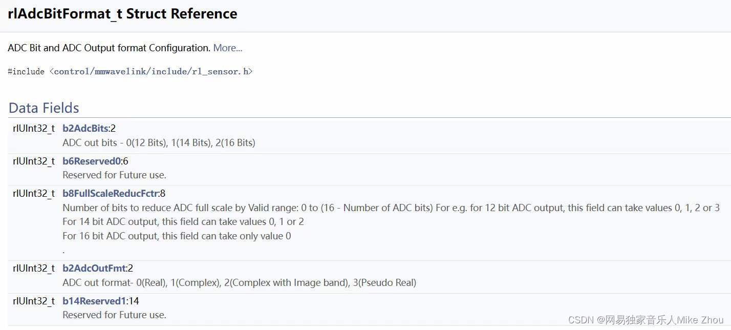
这个函数要传一个结构体进去 然后结构体里面有个adcoutcfg结构体变量 adcoutcfg结构体里面共有三个变量 一个adcbitformat结构体 另外两保留 点开adcbitformat结构体发现是个32位段 一共四级结构体 那么请问 为什么adcoutcfg变量不直接定义成一个32位无符号整形? 另外 0和1是使能还是不使能 可不可以统一一下 同一个变量里面两种规定
/*! \brief
* Rx/Tx Channel Configuration
*/
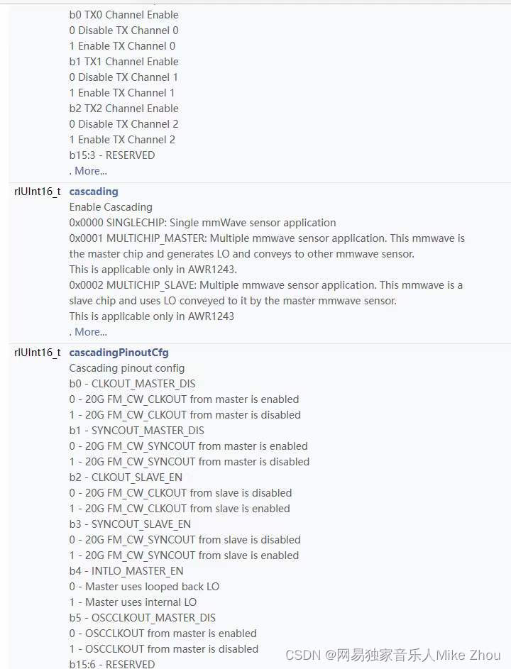
typedef struct rlChanCfg
{/*** @ brief  RX Channel Bitmap \nb0 RX0 Channel Enable \n0   Disable RX Channel 0 \n1   Enable RX Channel 0 \nb1 RX1 Channel Enable \n0   Disable RX Channel 1 \n1   Enable RX Channel 1 \nb2 RX2 Channel Enable \n0   Disable RX Channel 2 \n1   Enable RX Channel 2 \nb3 RX3 Channel Enable \n0   Disable RX Channel 3 \n1   Enable RX Channel 3 \nb15:4 - RESERVED \n*/rlUInt16_t rxChannelEn;/*** @brief  TX Channel Bitmap \nb0 TX0 Channel Enable \n0   Disable TX Channel 0 \n1   Enable TX Channel 0\nb1 TX1 Channel Enable \n0   Disable TX Channel 1 \n1   Enable TX Channel 1 \nb2 TX2 Channel Enable \n0   Disable TX Channel 2 \n1   Enable TX Channel 2 \nb15:3 - RESERVED \n@note : TX2 is supported only on some of the devices, Please refer device data \nsheet. \n*/rlUInt16_t txChannelEn;/*** @brief  Enable Cascading \n0x0000 SINGLECHIP: Single mmWave sensor application\n0x0001 MULTICHIP_MASTER: Multiple mmwave sensor application. This mmwave is \nthe master chip and generates LO and conveys to other mmwave sensor. \nThis is applicable only in AWR1243.\n0x0002 MULTICHIP_SLAVE: Multiple mmwave sensor application. This mmwave is a \nslave chip and uses LO conveyed to it by the master mmwave sensor. \nThis is applicable only in AWR1243 \n@note : Please refer device data sheet for cascading capability and 20G SYNCpins \n*/rlUInt16_t cascading;/*** @brief  Cascading pinout config \n*         b0 - CLKOUT_MASTER_DIS \n*              0 - 20G FM_CW_CLKOUT from master is enabled \n*              1 - 20G FM_CW_CLKOUT from master is disabled \n*         b1 - SYNCOUT_MASTER_DIS \n*              0 - 20G FM_CW_SYNCOUT from master is enabled \n*              1 - 20G FM_CW_SYNCOUT from master is disabled \n*         b2 - CLKOUT_SLAVE_EN \n*              0 - 20G FM_CW_CLKOUT from slave is disabled \n*              1 - 20G FM_CW_CLKOUT from slave is enabled \n*         b3 - SYNCOUT_SLAVE_EN \n*              0 - 20G FM_CW_SYNCOUT from slave is disabled \n*              1 - 20G FM_CW_SYNCOUT from slave is enabled \n*         b4 - INTLO_MASTER_EN \n*              0 - Master uses looped back LO \n*              1 - Master uses internal LO \n*         b5 - OSCCLKOUT_MASTER_DIS \n*              0 - OSCCLKOUT from master is enabled \n*              1 - OSCCLKOUT from master is disabled \n*      b15:6 - RESERVED \n*/rlUInt16_t cascadingPinoutCfg;
}rlChanCfg_t;
typedef struct rlAdcBitFormat
{/*** @brief  ADC out bits - 0(12 Bits), 1(14 Bits), 2(16 Bits)*/rlUInt32_t b2AdcBits           :2;/*** @brief  Reserved for Future use*/rlUInt32_t b6Reserved0        :6;/*** @brief Number of bits to reduce ADC full scale byValid range: 0 to (16 - Number of ADC bits)For e.g. for 12 bit ADC output, this field can take values 0, 1, 2 or 3 \nFor 14 bit ADC output, this field can take values 0, 1 or 2 \nFor 16 bit ADC output, this field can take only value 0 \n*/rlUInt32_t b8FullScaleReducFctr:8;/*** @brief  ADC out format- 0(Real), 1(Complex), 2(Complex with Image band), 3(Pseudo Real)*/rlUInt32_t b2AdcOutFmt         :2;/*** @brief  Reserved for Future use*/rlUInt32_t b14Reserved1        :14;
}rlAdcBitFormat_t;
